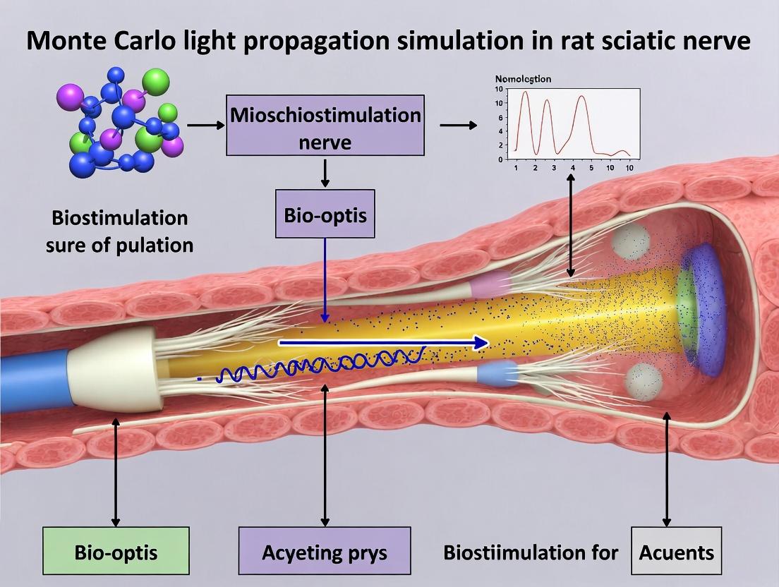
Modeling Light Transport in Neural Tissue: A Monte Carlo Approach to Rat Sciatic Nerve Biostimulation
This article provides a comprehensive guide for researchers and biomedical engineers on applying Monte Carlo (MC) simulations to model light propagation for optical biostimulation of the rat sciatic nerve.
Modeling Light Transport in Neural Tissue: A Monte Carlo Approach to Rat Sciatic Nerve Biostimulation
Abstract
This article provides a comprehensive guide for researchers and biomedical engineers on applying Monte Carlo (MC) simulations to model light propagation for optical biostimulation of the rat sciatic nerve. We explore the foundational principles of light-tissue interaction, detail the methodological steps for building accurate computational models of nerve tissue, and address common challenges in parameter selection and model validation. By comparing MC methods with alternative modeling techniques, we demonstrate their critical role in optimizing stimulation parameters, predicting irradiation thresholds, and advancing the development of precise, non-invasive neuromodulation therapies for pain management and nerve repair.
Principles of Light in Nerves: Core Physics for Sciatic Nerve Biostimulation
Scientific Rationale and Context
Optical neuromodulation is a precise technique for controlling neuronal activity using light, often via optogenetic actuators or direct infrared neural stimulation. In the context of a thesis investigating Monte Carlo light propagation modeling for rat sciatic nerve biostimulation, targeting this nerve is critical for translational peripheral nerve research.
The rat sciatic nerve is a standard in vivo model due to its:
- Accessibility and size: Its large diameter (~1 mm) allows for consistent surgical exposure and placement of optical or stimulating devices.
- Well-characterized anatomy and function: Its mixed sensory/motor composition enables evaluation of both afferent and efferent signals. Evoked compound muscle action potentials (CMAPs) and sensory nerve action potentials (SNAPs) provide robust quantitative readouts.
- Translational relevance: Findings directly inform research on pain management, neuroprosthetics, and functional recovery from nerve injury—key areas for drug and device development.
Monte Carlo simulations of light transport are essential to design effective optical stimulation protocols. They model how photons scatter and absorb in neural tissue, predicting the spatial distribution of light energy and optimal parameters (wavelength, power, fiber placement) to achieve specific neuromodulation outcomes.
Key Data & Parameters for Optical Stimulation
The following tables summarize critical quantitative parameters from recent literature relevant to optical stimulation of the rat sciatic nerve.
Table 1: Common Optogenetic Parameters for Rat Sciatic Nerve Stimulation
| Parameter | Typical Range | Notes & Impact |
|---|---|---|
| Opsin | Channelrhodopsin-2 (ChR2), Chronos | ChR2 most common; Chronos for faster kinetics. |
| Target Expression | DRG neurons (sensory), motoneurons (motor) | AAV serotypes (e.g., AAV6, AAV8) used for retrograde labeling. |
| Excitation Wavelength | 450 - 470 nm (blue light) | Peak absorption for ChR2. |
| Light Power at Nerve | 1 - 20 mW | Dependent on opsin expression level and transduction efficiency. |
| Pulse Duration | 1 - 50 ms | Longer pulses recruit more axons; affects temporal fidelity. |
| Stimulation Frequency | 1 - 40 Hz | Higher frequencies can induce tetanic muscle contraction. |
Table 2: Infrared Neural Stimulation (INS) Parameters for Rat Sciatic Nerve
| Parameter | Typical Range | Physiological Basis & Monte Carlo Relevance |
|---|---|---|
| Wavelength | 1450 - 2120 nm | High water absorption leads to localized thermal gradient. |
| Pulse Energy | 0.1 - 1.0 J | Energy dictates volume of tissue heated above threshold (~3-7°C rise). |
| Pulse Width | 100 µs - 10 ms | Critical for heat confinement; shorter pulses reduce thermal diffusion. |
| Spot Diameter | 300 - 600 µm | Defines initial photon distribution; key input for Monte Carlo model. |
| Radial Penetration Depth | ~0.5 - 1.0 mm | Estimated for 1470-1550 nm; determined via Monte Carlo simulation. |
Detailed Experimental Protocols
Protocol 1: Monte Carlo Simulation for Optical Parameter Design
Aim: To model light distribution in rat sciatic nerve tissue for designing an optical stimulation experiment. Materials: Simulation software (e.g., MCML, TIM-OS, custom MATLAB/Python code). Steps:
- Define Optical Properties: Input wavelength-specific coefficients for absorption (µa) and reduced scattering (µs') for rat nerve tissue (e.g., epidermis, fat, nerve trunk) into the model. Example values for 1470 nm: µa ~ 25 cm⁻¹, µs' ~ 8 cm⁻¹.
- Set Source Geometry: Define optical fiber parameters (core diameter, NA) and its distance from/placement on the nerve.
- Run Simulation: Launch Monte Carlo simulation with 10⁷ - 10⁹ photons to ensure statistical accuracy.
- Output Analysis: Generate 2D/3D maps of fluence rate (W/cm²) and absorbed energy density (J/cm³). Determine the photon density at the target fascicle depth.
- Parameter Optimization: Iteratively adjust source power, wavelength, and placement in the simulation to achieve target fluence at depth while minimizing surface exposure.
Protocol 2:In VivoOptical Stimulation of Rat Sciatic Nerve
Aim: To elicit and record measurable motor or sensory responses via optical stimulation. Materials: Anesthetized rat model, surgical tools, laser or LED system, optical fiber and ferrule, electrophysiology setup (EMG needles, recording electrodes, amplifier, data acquisition system). Steps:
- Surgical Exposure: Anesthetize rat and perform a lateral thigh incision. Gently dissect to expose the sciatic nerve, keeping the epineurium and blood supply intact. Maintain moisture with saline.
- Device Placement: Secure a low-NA optical fiber (e.g., 200 µm core) in a stereotaxic holder perpendicular to and lightly touching the nerve sheath. Place bipolar recording electrodes in the target muscle (e.g., gastrocnemius for motor) or distally on the nerve trunk (for sensory).
- Stimulation Protocol: Deliver light pulses (parameters from Table 1 or 2) using a controlled driver. Start at low power/energy, incrementally increasing until a threshold response is observed.
- Data Acquisition: Record evoked EMG (CMAP) or nerve (SNAP) signals. Average multiple trials (n=5-10) to improve signal-to-noise ratio. Measure latency, amplitude, and area under the curve.
- Post-experiment: Euthanize animal per protocol. Optionally, harvest nerve for histology to correlate stimulation site with anatomy or opsin expression.
Signaling and Experimental Pathways
Diagram 1: Workflow for Optical Neuromodulation Experiment Design
Diagram 2: Logic of Monte Carlo Photon Transport in Neural Tissue
The Scientist's Toolkit: Research Reagent Solutions
Table 3: Essential Materials for Rat Sciatic Nerve Optical Neuromodulation
| Item / Reagent | Function & Rationale |
|---|---|
| AAV-hSyn-ChR2(H134R)-eYFP | Drives cell-type-specific (neuronal) expression of the light-gated cation channel Channelrhodopsin-2 for optogenetic activation. |
| Infrared Diode Laser (1470 nm or 1550 nm) | Provides high-power, pulsed infrared light for transient thermal stimulation (INS) without genetic modification. |
| Low-OH Optical Fiber (200/220 µm core) | Delivers light from source to nerve with minimal loss, especially critical for infrared wavelengths. |
| Neuromuscular Blocking Agent (e.g., Vecuronium) | Used in specific protocols to isolate direct nerve responses from indirect muscle activation artifacts. |
| Artificial Cerebrospinal Fluid (aCSF) | Maintains ionic balance and moisture of the exposed nerve during surgery to preserve tissue health and electrophysiological viability. |
| Ketamine/Xylazine Cocktail | Standard injectable anesthetic regimen providing stable surgical plane for rodent in vivo nerve procedures. |
| Platinum/Iridium Bipolar Hook Electrodes | Low-impedance, inert recording electrodes for high-fidelity capture of compound nerve action potentials (CNAPs). |
| GraphPad Prism / MATLAB | Software for statistical analysis and visualization of electrophysiological data (latency, amplitude, recruitment curves). |
Quantitative Data on Optical Properties of Neural Tissue
The efficacy of optical neuromodulation, particularly in the context of Monte Carlo simulations for rat sciatic nerve biostimulation, hinges on precise optical parameters. The following tables summarize critical values from current literature.
Table 1: Optical Properties of Rat Peripheral Nerve Tissue at Common Biostimulation Wavelengths
| Wavelength (nm) | Absorption Coefficient µa (cm⁻¹) | Reduced Scattering Coefficient µs' (cm⁻¹) | Anisotropy Factor (g) | Reference Tissue Type |
|---|---|---|---|---|
| 650 | 0.1 - 0.3 | 10 - 14 | 0.85 - 0.92 | Rat Sciatic Nerve (ex vivo) |
| 808 | 0.15 - 0.25 | 8 - 12 | 0.88 - 0.94 | Rat Sciatic Nerve (in vivo) |
| 980 | 0.3 - 0.7 | 7 - 10 | 0.89 - 0.95 | Neural Tissue (model) |
| 1064 | 0.2 - 0.4 | 6 - 9 | 0.90 - 0.96 | Myelinated Nerve |
Table 2: Key Light-Tissue Interaction Parameters for Monte Carlo Simulation
| Parameter | Symbol | Typical Value Range | Significance in Simulation |
|---|---|---|---|
| Refractive Index | n | 1.36 - 1.45 | Governs reflection/refraction at boundaries. |
| Penetration Depth (δ) | δ = 1 / √(3µa(µa+µs')) | 2 - 5 mm (at 808 nm) | Estimates depth of effective light propagation. |
| Albedo | a = µs / (µa + µs) | 0.99 - 0.999 | Probability of scattering vs. absorption per event. |
| Photon Weight Threshold | W_th | 10^-4 - 10^-6 | Terminates photon packets to speed up simulation. |
Application Notes for Monte Carlo Modeling in Sciatic Nerve Biostimulation
Note 1: Anisotropy Modeling. The high anisotropy factor (g > 0.85) in neural tissue necessitates the use of the Henyey-Greenstein phase function in Monte Carlo simulations. This accurately models the strong forward scattering caused by cylindrical myelinated axons and collagen fibers, which is critical for predicting fluence distribution in the sciatic nerve bundle.
Note 2: Layered Tissue Structure. The rat sciatic nerve is not homogeneous. A three-layer model (epineurium, perineurium, endoneurium/fascicle) with distinct optical properties (µa, µs', g, n) significantly improves simulation accuracy for predicting photon migration and localized absorption leading to photobiomodulation or thermal effects.
Note 3: Wavelength Selection Rationale. Near-infrared (NIR) wavelengths (800-1100 nm) are preferred for deep-tissue biostimulation due to the "optical window" where absorption by hemoglobin and water is minimized, allowing greater penetration. The choice between 808 nm and 980 nm involves a trade-off between lower water absorption (808 nm) and potential for stronger neural absorption chromophores (980 nm).
Experimental Protocols
Protocol 1: Measurement of Ex Vivo Rat Sciatic Nerve Optical Properties Using Integrating Sphere
Objective: To determine the absorption (µa) and reduced scattering (µs') coefficients for input into Monte Carlo models.
Materials: See "Scientist's Toolkit" below.
Procedure:
- Nerve Harvesting: Euthanize adult Sprague-Dawley rat per IACUC protocol. Dissect to expose and carefully excise a 3-4 cm segment of the sciatic nerve. Rinse in chilled phosphate-buffered saline (PBS).
- Sample Preparation: Mount the nerve segment flat on a UV-fused silica slide (low scattering). Ensure no air gaps. Cover with a thin glass coverslip.
- System Calibration: Perform baseline calibration of the integrating sphere system (with laser source and spectrometer) using a reflectance standard (e.g., Spectralon) and a dark measurement.
- Total Transmittance (Tt) Measurement: Place the nerve sample at the sphere's entrance port. Illuminate with a collimated beam from a tunable laser (e.g., 650, 808, 980 nm). Measure the total transmitted light (both collimated and diffuse) collected by the sphere.
- Total Reflectance (Rt) Measurement: Move the sample to the sphere's sample port. Illuminate and measure the total light reflected back into the sphere.
- Collimated Transmittance (Tc) Measurement: Use a separate setup with a small aperture detector at a distance to measure only the collimated, non-scattered light transmitted through the sample.
- Data Analysis: Input Tt, Rt, and Tc measurements into an inverse adding-doubling (IAD) algorithm or similar inverse Monte Carlo fitting routine to extract µa and µs'. The anisotropy factor (g) is often assumed (~0.9) or taken from literature for the initial iteration.
- Replication: Repeat measurements on at least N=5 nerve samples from different animals. Store data at 4°C in PBS during measurements to minimize degradation.
Protocol 2: Monte Carlo Simulation of Light Propagation in Rat Sciatic Nerve
Objective: To model the spatial distribution of light fluence (J/cm²) within a rat sciatic nerve during a typical biostimulation experiment.
Materials: High-performance computing workstation, Monte Carlo simulation software (e.g., MCX, tMCimg, or custom code in Python/MATLAB).
Procedure:
- Define Simulation Volume: Create a 3D voxelated volume (e.g., 100 x 100 x 200 voxels, 0.01 mm³/voxel) representing the tissue geometry.
- Assign Optical Properties: Populate the volume with optical properties from Table 1 (e.g., for 808 nm). Define a layered structure if applicable. Assign a surrounding medium (e.g., air or saline) with appropriate refractive index.
- Configure Source: Define a Gaussian beam source profile with diameter matching the experimental optical fiber (e.g., 200 µm). Set the source position and orientation perpendicular to the nerve's long axis.
- Set Simulation Parameters: Launch 10^7 to 10^8 photon packets. Set the photon weight threshold (W_th) to 10^-5. Use the Henyey-Greenstein phase function.
- Run Simulation: Execute the simulation on a GPU-accelerated platform for speed.
- Output Analysis: Generate 2D/3D maps of fluence rate, absorption density, and penetration depth. Extract a line profile of fluence along the nerve's central axis and depth.
- Validation (Optional): Compare simulated surface reflectance/transmittance values with simple experimental measurements from Protocol 1 to validate the model.
Visualizations
Title: Monte Carlo Photon Propagation Algorithm Flowchart
Title: Photon Interaction & Biostimulation Pathway
The Scientist's Toolkit: Research Reagent & Material Solutions
Table 3: Essential Materials for Optical Property Measurement & Simulation
| Item | Function / Rationale | Example Product / Specification |
|---|---|---|
| Tunable Near-IR Laser Source | Provides monochromatic light at specific wavelengths (e.g., 808, 980 nm) for controlled tissue interrogation and simulation source definition. | Thorlabs ITC4001 with LP980-SF50 laser diode. |
| Integrating Sphere with Detectors | Measures total reflectance (Rt) and total transmittance (Tt) of tissue samples, the primary data for inverse optical property calculation. | Sphere diameter >100mm, with InGaAs and Si detectors. |
| Inverse Adding-Doubling (IAD) Software | Algorithm to calculate µa and µs' from measured Rt and Tt. Critical for deriving simulation inputs. | Open-source IAD code (Prahl) or commercial equivalent. |
| GPU-Accelerated Monte Carlo Platform | Enables rapid simulation of millions of photon packets in complex 3D tissue geometries. Essential for practical modeling. | NVIDIA GPU (RTX 5000+) with MCX (Monte Carlo eXtreme) software. |
| UV-Fused Silica Slides & Coverslips | Sample substrates with minimal autofluorescence and scattering to avoid interference with nerve tissue measurements. | Coverslip thickness #1.5 (0.17 mm). |
| Spectralon Reflectance Standard | Provides >99% diffuse reflectance for calibration of the integrating sphere system, ensuring measurement accuracy. | Labsphere Spectralon SRS-99. |
| Index-Matching Fluid | Reduces surface specular reflection at tissue-glass-air interfaces during measurement, improving accuracy. | Glycerol-water mixture (n~1.38). |
This application note details the structural and optical properties of the rat sciatic nerve, a critical target for neuromodulation techniques, including optical stimulation. Precise knowledge of its anatomy and optical characteristics is foundational for developing accurate Monte Carlo (MC) models that simulate light-tissue interaction. These models are essential for predicting light penetration, energy deposition, and optimal parameters for effective and safe biostimulation in preclinical research for pain management and neurodegenerative diseases.
Layered Anatomical Structure & Optical Implications
The rat sciatic nerve is a mixed peripheral nerve with a complex, hierarchical organization. Each layer presents distinct optical properties (scattering, absorption) that influence light propagation during optical stimulation.
Table 1: Layered Structural and Optical Properties of the Rat Sciatic Nerve
| Layer | Primary Composition | Estimated Thickness (Rat) | Key Optical Property (at ~650-1550 nm) | Role in Light Propagation |
|---|---|---|---|---|
| Epineurium | Dense, fibrous collagen; adipocytes; blood vessels. | 50 - 150 µm | High scattering (collagen fibers) | Primary scattering layer; attenuates and diffuses incident light. |
| Perineurium | Concentric layers of flattened perineurial cells (epithelioid), collagen. | 10 - 20 µm per fascicle sheath | Moderate scattering and absorption (cellular layers) | Selective barrier; causes additional scattering and slight absorption. |
| Endoneurium | Collagen fibrils (Type III), fibroblasts, capillary network within fascicle. | Inter-axonal matrix | Moderate scattering (collagen network) | Main intrafascicular scattering medium; surrounds individual axons. |
| Myelinated Axons | Axon core (cytoplasm) surrounded by multi-lamellar myelin (lipid-protein). | Diameter: 2-15 µm (incl. myelin) | High scattering & absorption. Myelin is a strong scatterer. | Primary targets for stimulation; dominant source of scattering and absorption. |
| Unmyelinated Axons | Axons enveloped by Remak cell cytoplasm. | Diameter: 0.2-1.5 µm | Lower scattering than myelinated axons. | Less attenuating; require different energy thresholds for activation. |
Key Quantitative Optical Properties for MC Modeling
Effective MC simulation requires input of wavelength-dependent optical coefficients: the absorption coefficient (µa), scattering coefficient (µs), anisotropy factor (g), and reduced scattering coefficient (µs' = µs(1-g)).
Table 2: Representative Optical Coefficients for Rat Sciatic Nerve Components (Values are approximate and wavelength-dependent; consult specific literature for your target wavelength)
| Tissue Component | Wavelength ~650 nm | Wavelength ~1064 nm | Wavelength ~1550 nm | Notes |
|---|---|---|---|---|
| Whole Nerve (Avg.) | µa: 0.2-0.5 cm⁻¹µs': 15-25 cm⁻¹ | µa: 0.3-0.7 cm⁻¹µs': 8-15 cm⁻¹ | µa: 1.0-2.5 cm⁻¹µs': 5-10 cm⁻¹ | Highly variable based on fat/collagen content. |
| Myelin (Key Scatterer) | High µs, g ~0.9-0.95 | High µs, g ~0.9-0.95 | Increased µa (water absorption) | Lamellar structure causes strong forward scattering (high g). |
| Collagen (Epineurium) | High µs', g ~0.8-0.9 | Moderate µs' | Moderate µs' | Primary source of scattering in connective sheaths. |
| Blood (Vessels) | µa >> nerve (Hb absorption) | µa lower than at 650nm | µa low | Significant local absorber, especially at visible wavelengths. |
Experimental Protocols
Protocol 1: Measurement of Nerve Layer-Specific Optical Properties Using Integrating Sphere
Objective: To determine µa and µs' of isolated epineurial and fascicular tissue.
Materials: See "Scientist's Toolkit" below. Procedure:
- Nerve Dissection & Micro-dissection: Excise rat sciatic nerve (see Protocol 2). Under a surgical microscope, carefully separate the epineurium using fine forceps and micro-scissors. Collect the underlying fascicular tissue.
- Sample Preparation: Place each tissue sample (epineurium, fascicle) between two thin, optically clear glass slides or quartz cuvettes with a known, controlled thickness (e.g., 200 µm) using spacers. Keep hydrated with saline.
- Integrating Sphere Measurement:
- Calibrate the integrating sphere system with a reference standard.
- Place the sample at the sphere's input port.
- Measure the total reflectance (RT) and total transmittance (TT) using a tunable laser or monochromator across desired wavelengths (e.g., 600-1600 nm).
- Perform an additional measurement for the collimated transmittance (TC).
- Data Analysis: Use an inverse adding-doubling (IAD) or inverse Monte Carlo algorithm to compute µa and µs' from the measured RT and TT data. The collimated transmission helps estimate the scattering coefficient (µs) and anisotropy (g).
Protocol 2: Surgical Exposure of the Rat Sciatic Nerve forIn VivoOptical Stimulation
Objective: To reproducibly expose the sciatic nerve for in vivo light delivery and electrophysiological recording.
Procedure:
- Anesthesia & Preparation: Anesthetize rat (e.g., isoflurane 2-4%). Shave and sterilize the lateral thigh area. Place animal in lateral recumbency.
- Incision: Make a ~2 cm skin incision along the line from the posterior iliac spine to the lateral knee.
- Muscle Blunt Dissection: Use blunt forceps to separate the biceps femoris and gluteus superficialis muscles. Retract muscles using small retractors.
- Nerve Identification & Isolation: Identify the glistening white sciatic nerve trunk deep to the biceps femoris. Carefully clear away surrounding loose connective tissue (paraneural fat) using fine forceps and micro-dissection scissors.
- Nerve Cradle Placement: Gently lift the nerve and place it onto a custom-designed, black-anodized metal or silicone nerve cradle. This stabilizes the nerve, minimizes movement, and provides a consistent geometry for light application.
- Moisture Maintenance: Continuously irrigate the exposed nerve with warm, sterile physiological saline to prevent desiccation.
- Stimulation & Recording: Position the optical fiber (e.g., 400 µm core) perpendicularly and at a fixed distance (e.g., 1 mm) above the nerve. Place recording electrodes in the target musculature (e.g., gastrocnemius) for compound muscle action potential (CMAP) measurement.
Diagrams & Visual Workflows
Monte Carlo Simulation Workflow for Nerve Stimulation
Light Propagation Through Nerve Layers
The Scientist's Toolkit: Essential Research Reagents & Materials
| Item | Function & Application |
|---|---|
| Isoflurane/Oxygen Mix | Safe, controllable inhalation anesthesia for in vivo rodent surgery. |
| Sterile Physiological Saline (0.9%) | Irrigation to maintain tissue hydration and prevent desiccation during experiments. |
| Integrating Sphere System | Equipped with tunable laser; for measuring total reflectance/transmittance of tissue samples to derive µa and µs'. |
| Micro-dissection Tools | Fine forceps (e.g., Dumont #5), spring scissors, Vannas scissors; for precise nerve sheath dissection. |
| Black-Anodized Nerve Cradle | Provides a stable, non-reflective platform for the exposed nerve, standardizing light-target geometry. |
| Optical Fiber (Low-OH, 400µm Core) | For precise delivery of near-infrared (NIR) laser light to the nerve surface. |
| Tungsten Micro-electrodes | For high-fidelity recording of compound nerve action potentials (CNAP) or muscle (CMAP) signals. |
| Inverse Adding-Doubling (IAD) Software | Algorithm to compute optical coefficients from integrating sphere measurement data. |
| Monte Carlo Simulation Software (e.g., MCX, TIM-OS) | Customizable platform for modeling light propagation in the multi-layered nerve geometry. |
This document, framed within a thesis on Monte Carlo (MC) light propagation for rat sciatic nerve biostimulation, outlines the application of MC statistical modeling to photon transport. Precise understanding of light-tissue interaction (absorption, scattering) is critical for optimizing optical neuromodulation parameters (wavelength, power, beam profile) to achieve specific neurophysiological outcomes while minimizing thermal damage.
Core Data on Tissue Optical Properties & Simulation Parameters
Table 1: Representative Optical Properties of Rat Sciatic Nerve & Surrounding Tissue at Common Biostimulation Wavelengths
| Tissue Type / Parameter | Wavelength 808 nm | Wavelength 980 nm | Wavelength 1064 nm | Source / Notes |
|---|---|---|---|---|
| Sciatic Nerve (μₐ [cm⁻¹]) | 0.35 - 0.45 | 0.30 - 0.38 | 0.25 - 0.32 | Primary chromophores: water, hemoglobin. |
| Sciatic Nerve (μₛ' [cm⁻¹]) | 12.5 - 15.5 | 10.8 - 13.2 | 9.5 - 11.5 | Reduced scattering coefficient. |
| Muscle (μₐ [cm⁻¹]) | 0.40 - 0.55 | 0.35 - 0.45 | 0.30 - 0.40 | Surrounding tissue in exposure field. |
| Muscle (μₛ' [cm⁻¹]) | 11.0 - 14.0 | 9.5 - 12.0 | 8.5 - 10.5 | Anisotropy factor (g) typically ~0.9. |
| Fat / Epineurium (μₐ [cm⁻¹]) | 0.15 - 0.25 | 0.18 - 0.28 | 0.20 - 0.30 | Affects superficial photon distribution. |
| Monte Carlo Simulation Photons | 10⁷ - 10⁹ | 10⁷ - 10⁹ | 10⁷ - 10⁹ | Required for <2% statistical uncertainty. |
| Typical Irradiance at Target | 0.5 - 2.0 W/cm² | 0.5 - 2.0 W/cm² | 0.5 - 2.0 W/cm² | Model-derived for stimulation threshold. |
Table 2: Key Output Metrics from Monte Carlo Modeling for Protocol Design
| Output Metric | Description | Relevance to Biostimulation Protocol |
|---|---|---|
| Fluence Rate [W/cm²] | Total radiant power at a point. | Determines local energy deposition. |
| Absorbed Energy Density [J/cm³] | Spatial map of photon absorption. | Correlates with thermal rise & photobiomodulation. |
| Penetration Depth [mm] | Depth at which fluence drops to 1/e. | Informs wavelength choice for deep nerve targeting. |
| Volume of Activation | Tissue volume above irradiance threshold. | Estimates number of axons potentially stimulated. |
| Surface Reflectance | Fraction of light back-scattered. | Impacts safety and required laser power setting. |
Experimental Protocols
Protocol 3.1: MC Simulation for Pre-Experimental Parameter Optimization
Objective: To determine the required laser power and beam profile to deliver target fluence to rat sciatic nerve at a specific depth.
Materials: High-performance computing workstation, validated MC simulation software (e.g., MCX, tMCimg, or custom code), dataset of tissue optical properties (Table 1).
Procedure:
- Define Geometry: Construct a 3D layered model (e.g., skin, fat, muscle, nerve) with dimensions based on rat anatomy (e.g., 20x20x15 mm³).
- Assign Properties: Populate each layer with wavelength-specific absorption (μₐ), scattering (μₛ), anisotropy (g), and refractive index (n) from Table 1.
- Configure Source: Define source as a Gaussian beam (e.g., 1-3 mm FWHM) or flat-top profile at the skin surface.
- Run Simulation: Launch simulation with 10⁸ photon packets. Record photon trajectory, absorption events, and boundary events.
- Post-Process: Generate 3D maps of fluence rate and absorbed energy density. Extract the fluence at the centroid of the sciatic nerve model.
- Calculate Power: Reverse-calculate the required input laser power (Pinput) to achieve the target therapeutic fluence (Φtarget) at the nerve: Pinput = Φtarget * Asurface / (Tsurface * Ffactor), where Asurface is beam area, Tsurface is simulated transmittance, and Ffactor is the model-derived fluence normalization factor.
Protocol 3.2: Validation via Phantom Measurement
Objective: To validate the MC model predictions using a tissue-simulating phantom.
Materials: Liquid phantom (Intralipid, India ink, water), optical power meter, detector fiber probe, diode laser (808 nm), translation stage.
Procedure:
- Phantom Fabrication: Prepare a phantom with optical properties (μₐ, μₛ') matching those used in the MC simulation for muscle tissue.
- MC Prediction: Run simulation for the phantom geometry and laser source. Predict fluence rate along a line from the surface.
- Experimental Measurement: Immerse a isotropic detector probe connected to a power meter into the phantom. Irradiate the phantom surface with the laser at a fixed power.
- Data Collection: Measure fluence rate (via isotropic detection) at multiple depths by moving the probe with the translation stage.
- Validation: Compare the measured depth-dependent fluence rate profile with the MC-simulated profile. A correlation coefficient >0.95 validates the model for that property set.
Visualizations
Title: MC Modeling Workflow for Biostimulation
Title: Stochastic Photon-Tissue Interaction Fate
The Scientist's Toolkit: Research Reagent & Solution Guide
Table 3: Essential Materials for MC-Guided Biostimulation Research
| Item / Reagent | Function / Rationale | Example/Specification |
|---|---|---|
| MC Simulation Platform | Core tool for modeling stochastic photon transport and predicting light distribution in complex tissues. | MCX (GPU-accelerated), tMCimg, TIM-OS. |
| High-Fidelity Optical Property Database | Accurate input parameters (μₐ, μₛ', g, n) for each tissue layer at the research wavelength are critical for model validity. | Compiled from peer-reviewed literature or inverse adding-doubling measurements. |
| Tissue-Simulating Phantoms | For empirical validation of MC model predictions in a controlled, reproducible medium. | Liquid (Intralipid + ink) or solid (PDMS with TiO₂ & ink) phantoms with tunable properties. |
| Isotropic Detector Probe | Measures spatial fluence rate within phantoms or tissues, essential for model validation. | 0.8mm diameter spherical-tip fiber optic coupled to a calibrated photodiode/spectrometer. |
| Precision Optical Power Meter | Calibrates laser output and validates absolute power levels used in simulation and experiment. | Thermopile or integrating sphere sensor, NIST-traceable calibration. |
| Diode Laser Systems | Light source for in vivo biostimulation. Wavelength must match simulation. Modulation capability is key. | 808nm, 980nm, 1064nm with TTL modulation, output power >500mW. |
| Acute/Nerve Recording Setup | To measure the physiological output (e.g., compound action potential) of the simulated biostimulation protocol. | Hook electrodes, differential amplifier, data acquisition system, rodent nerve chamber. |
Current Research Landscape and Applications in Preclinical Models
Preclinical models, particularly rodent models, are indispensable for investigating the mechanisms and efficacy of novel therapeutic interventions. This application note is framed within a specific research thesis exploring Monte Carlo simulations of light propagation for precise optogenetic biostimulation of the rat sciatic nerve. The objective is to correlate simulated photon distributions with electrophysiological outcomes to optimize non-invasive neuromodulation. The broader landscape leverages such tailored models for disease modeling, target validation, and therapeutic safety assessment.
Table 1: Quantitative Data on Preclinical Sciatic Nerve Models
Data compiled from recent studies (2022-2024) utilizing rat sciatic nerve models for biostimulation and pain research.
| Parameter | Optogenetic Stimulation | Electrical Stimulation | Photobiomodulation (Therapy) |
|---|---|---|---|
| Common Model Species | Thy1-ChR2 transgenic Sprague-Dawley rat | Wild-type Sprague-Dawley or Wistar rat | Wistar rat (neuropathy model) |
| Stimulus Parameters | 473 nm laser, 5-15 ms pulses, 10-20 Hz, 5-10 mW/mm² | 0.1-0.5 mA, 0.1 ms pulse width, 1-10 Hz | 808-980 nm laser, 100-350 mW, continuous wave |
| Primary Readout | Compound Motor Action Potential (CMAP) amplitude | CMAP amplitude & latency | Mechanical allodynia threshold (g) |
| Typely Observed Outcome | CMAP amplitude increase of 60-80% from baseline | Direct, linear recruitment with current increase | 50-150% increase in paw withdrawal threshold |
| Key Advantage | Cell-type specificity; minimal off-target effects | Standardized, reliable recruitment | Non-thermal, modulatory therapeutic effect |
Application Note: Integrating Monte Carlo Simulation withIn VivoOptogenetic Protocols
Objective: To validate a Monte Carlo photon migration model by correlating simulated fluence rate distributions in rat hindlimb tissue with evoked electrophysiological responses from sciatic nerve optogenetic stimulation.
Background: The thesis core involves developing a multi-layered (skin, muscle, nerve) Monte Carlo model for 473 nm light. Accurate prediction of light delivery is critical for achieving reproducible, sub-thermal optogenetic activation without tissue damage.
Protocol 1: Monte Carlo Simulation of Light Propagation for Protocol Planning
Aim: To compute the spatial distribution of light fluence within the rat hindlimb to guide optogenetic probe placement.
Materials & Software:
- Software: Monte Carlo modeling software (e.g., MCX, TIM-OS, or custom code in MATLAB/Python).
- Input Parameters: 3D mesh or layered model of rat hindlimb anatomy from MRI/atlas.
- Optical Properties Table: (Defined at 473 nm).
- Simulation Engine: High-performance computing cluster or GPU-enabled workstation.
Methodology:
- Model Construction: Create a simplified 3-layer cylindrical model (skin: 0.5 mm, muscle: 4 mm, nerve: 1 mm diameter). Set model dimensions to 10x10x15 mm.
- Define Optical Properties: Assign absorption (μa) and reduced scattering (μs') coefficients for each layer at 473 nm (see Table 2).
- Source Definition: Configure a pencil beam source positioned 1 mm above the skin surface, oriented perpendicularly.
- Photon Launch: Simulate 1 x 10⁸ photon packets to ensure low statistical uncertainty.
- Data Output: Export the 3D fluence rate map. Plot the fluence profile along the central axis descending through the nerve layer.
Table 2: Sample Optical Properties for Monte Carlo Model (473 nm)
| Tissue Layer | Absorption Coefficient μa (mm⁻¹) | Reduced Scattering Coefficient μs' (mm⁻¹) | Refractive Index (n) |
|---|---|---|---|
| Skin | 0.10 | 3.5 | 1.37 |
| Muscle | 0.05 | 2.0 | 1.41 |
| Nerve | 0.08 | 1.8 | 1.40 |
Protocol 2:In VivoValidation via Sciatic Nerve Optogenetic Biostimulation
Aim: To experimentally measure motor response thresholds and correlate them with simulated fluence at the target nerve.
The Scientist's Toolkit: Research Reagent Solutions
| Item/Catalog # | Function in Experiment |
|---|---|
| Thy1-ChR2-YFP Transgenic Rat (Line 9) | Expresses Channelrhodopsin-2 in motor neurons, enabling specific optical stimulation. |
| 473 nm Diode-Pumped Solid-State Laser | Provides the precise blue light wavelength required to activate ChR2. |
| Programmable Laser Driver & Pulse Generator | Delivers controlled light pulses (duration, frequency, power) synchronized with data acquisition. |
| Bipolar Platinum-Iridium Recording Hook Electrodes | For recording Compound Motor Action Potentials (CMAP) from target foot muscles. |
| Differential Amplifier & Data Acquisition System | Amplifies and digitizes microvolt-scale CMAP signals for analysis. |
| Isoflurane Anesthesia System | Maintains stable, adjustable surgical plane of anesthesia. |
| Sterile Surgical Tools (Fine Scissors, Forceps) | For careful dissection and exposure of the sciatic nerve. |
| Optical Power Meter & Photodiode Sensor | Calibrates laser output power at the fiber tip before and during experiments. |
Methodology:
- Animal Preparation: Anesthetize a Thy1-ChR2 rat. Maintain core temperature. Perform a lateral thigh incision to expose the sciatic nerve without damaging it.
- Probe Placement: Using the simulation map, position the cleaved tip of a 400 μm optical fiber perpendicularly 1 mm above the nerve at the predicted maximal fluence point.
- Electrophysiology Setup: Insert recording electrodes into the ipsilateral plantar foot muscles. Place a reference electrode nearby. Ground the animal.
- Stimulation Protocol: Deliver 10 ms pulses of 473 nm light at 1 Hz. Systematically increase laser power from 0.1 mW to 10 mW. At each power, record 10-20 CMAP traces.
- Data Collection: Measure peak-to-peak CMAP amplitude and latency for each trial. Calculate mean and standard deviation per power level.
- Correlation Analysis: Plot experimental CMAP amplitude vs. laser power. On a secondary axis, plot the simulated fluence rate at the nerve depth vs. laser power. Analyze the relationship between the two curves.
Visualization Diagrams
Monte Carlo-In Vivo Validation Workflow
Optogenetic Stimulation to CMAP Pathway
Building Your Simulation: A Step-by-Step Monte Carlo Model for Nerve Biostimulation
This application note details the protocols for constructing a geometrically accurate 3D model of a rat sciatic nerve, encompassing the internal fascicular structure and the surrounding epineurium. This model serves as a critical computational domain for Monte Carlo simulations of light propagation, enabling precise quantification of photon fluence for optogenetic and photobiomodulation studies in peripheral nerve biostimulation research.
Quantitative Anatomical Data for Model Parameterization
Accurate model construction relies on species-specific (rat) morphometric data. The following tables summarize key dimensions compiled from recent literature.
Table 1: Rat Sciatic Nerve Gross Dimensions
| Parameter | Mean Value (± SD) | Source / Strain | Notes |
|---|---|---|---|
| Total Nerve Diameter | 1.2 mm ± 0.2 mm | Sprague Dawley (Adult) | Measured at mid-thigh level. |
| Nerve Length (Model Segment) | 10.0 mm | N/A | Standard segment for simulation. |
| Number of Fascicles | 1 - 3 | Sprague Dawley | Commonly a single large fascicle or 2-3 smaller ones. |
| Epineurium Thickness | 80 - 150 µm | Wistar Rat | Variable, typically 10-15% of total radius. |
Table 2: Fascicular and Tissue Layer Optical Properties (λ = 473 nm & 635 nm)
| Tissue Layer | µa (cm⁻¹) 473nm | µs' (cm⁻¹) 473nm | µa (cm⁻¹) 635nm | µs' (cm⁻¹) 635nm | n (Refractive Index) |
|---|---|---|---|---|---|
| Epineurium | 0.8 | 120 | 0.3 | 90 | 1.37 |
| Perineurium | 1.1 | 150 | 0.4 | 110 | 1.38 |
| Endoneurium (Fascicle) | 0.5 | 110 | 0.2 | 80 | 1.36 |
| Myelinated Axon | 0.9 | 200 | 0.5 | 150 | 1.38 |
µa: Absorption coefficient; µs': Reduced scattering coefficient; n: Refractive index. Values are approximations from combined nerve, adipose, and collagen data.
Protocol: 3D Geometry Reconstruction Workflow
Protocol 1: Histology-Based Model Generation
Objective: To create a subject-specific 3D nerve geometry from histological cross-sections.
Materials:
- Perfusion-fixed rat sciatic nerve segment (10 mm).
- Cryostat or microtome.
- Histology stains (e.g., Hematoxylin and Eosin, Masson's Trichrome).
- Brightfield slide scanner.
- Image processing software (e.g., Fiji/ImageJ).
- 3D modeling software (e.g., Blender, COMSOL).
Procedure:
- Tissue Preparation & Sectioning: Embed the fixed nerve segment in OCT compound. Serially section the nerve transversely at 10 µm thickness. Collect every 10th section (resulting in 100 µm interval) on slides.
- Staining & Imaging: Stain slides with Masson's Trichrome to differentiate collagenous epineurium (blue/green) from neural tissue (red/purple). Scan slides at 20x magnification.
- Image Segmentation: a. In Fiji, align all sequential images using the "Linear Stack Alignment with SIFT" plugin. b. For each image, manually or semi-automatically (using thresholding) trace the contours of: (i) the outer nerve boundary (epineurium), (ii) the perineurium of each fascicle, and (iii) major blood vessels if present. c. Export each contour set as XY coordinate lists.
- 3D Model Assembly:
a. Import coordinate lists into 3D modeling software.
b. Loft or interpolate contours between sequential slices to generate smooth 3D surfaces for each structure.
c. Assign the enclosed volumes as distinct geometric domains:
epineurium_domain,perineurium_domain,fascicle_domain. d. Export the final geometry as an STL or STEP file compatible with your Monte Carlo simulation platform (e.g., MCX, TIM-OS).
Protocol 2: Parametric Model Generation for Sensitivity Analysis
Objective: To create a parameterized 3D nerve geometry for systematic variation of key anatomical features in simulation studies.
Materials:
- Scripting environment (Python with NumPy/SciPy, MATLAB).
- Parametric CAD software or scripting-based geometry kernel (e.g., OpenCASCADE via PythonOCC).
Procedure:
- Define Base Parameters: Set variables for
total_diameter,fascicle_count,fascicle_diameter_mean,epineurium_thickness. - Generate Fascicle Layout:
a. For a single fascicle model: Position a cylinder along the nerve's central axis with diameter =
total_diameter - 2*epineurium_thickness. b. For multi-fascicle models: Use a random sequential adsorption algorithm within the defined epineurial boundary to place non-overlapping fascicle cylinders with randomized diameters within a defined range. - Construct Layers:
a. Create the
fascicle_domainas the union of all fascicle cylinders. b. Create theperineurium_domainby generating a 5-10 µm thick shell around each fascicle. c. Create theepineurium_domainas an outer cylinder surrounding all inner structures, with its inner boundary defined by the outermost extent of the perineurium/fascicles. - Export and Iterate: Script the export of the geometry. Embed the script in a loop to automatically generate models across a defined parameter space (e.g., varying epineurium thickness from 50 to 150 µm).
Visualization of Workflows
Histology vs. Parametric 3D Model Generation
Monte Carlo Photon Path in Layered Nerve Model
The Scientist's Toolkit: Research Reagent Solutions
Table 3: Essential Materials for Geometry Definition & Validation
| Item | Function in Protocol | Example Product / Specification |
|---|---|---|
| Paraformaldehyde (4%) | Perfusion fixation to preserve native nerve geometry and prevent collapse. | Electron Microscopy Sciences, #15710 |
| O.C.T. Compound | Optimal Cutting Temperature medium for cryosectioning nerve tissue without distortion. | Sakura Finetek, #4583 |
| Masson's Trichrome Stain Kit | Differentiates collagen (epineurium/perineurium) from axons and myelin. | Sigma-Aldrich, #HT15 |
| Histology Slide Scanner | High-resolution digitization of entire tissue sections for accurate contouring. | Hamamatsu NanoZoomer S360 |
| Image Analysis Software | Alignment, segmentation, and quantitative morphometry of nerve cross-sections. | Fiji/ImageJ (Open Source) |
| Scripting Library for Geometry | Parametric generation and export of 3D nerve models. | Python with numpy-stl & pythonocc-core |
| Monte Carlo Simulation Platform | Simulates light propagation in the constructed 3D geometry. | MCX (Monte Carlo eXtreme) - GPU-accelerated |
Accurate sourcing and assignment of optical properties—absorption coefficient (μa), scattering coefficient (μs), anisotropy factor (g), and refractive index (n)—are foundational for Monte Carlo (MC) simulations of light propagation in biological tissues. In the specific thesis context of rat sciatic nerve biostimulation research, these parameters dictate the simulated light dose distribution, which is critical for interpreting photobiomodulation effects on nerve regeneration, pain mitigation, and drug delivery outcomes. Incorrect parameter values invalidate simulation results and subsequent biological conclusions.
The Optical Property Quadrad: Definitions and Impact
- μa (Absorption Coefficient): Probability of photon absorption per unit path length. In neural tissue, primary chromophores include hemoglobin, myelin, water, and cytochrome c oxidase.
- μs (Scattering Coefficient): Probability of photon scattering per unit path length. Dominated by cellular membranes, organelles, and myelin sheath structure in nerve tissue.
- g (Anisotropy Factor): Mean cosine of the scattering angle. Describes scattering directionality. High g values (~0.9) indicate forward-scattering, typical in biological tissues.
- n (Refractive Index): Ratio of light's speed in vacuum to its speed in the medium. Governs reflection and refraction at tissue layer interfaces.
Sourcing Optical Parameters: Current Data Synthesis
A live search of recent literature and databases (e.g., omlc.org, IOPTP, specific biophotonics journals) reveals data for peripheral nerve and analogous neural tissues. Key considerations include wavelength dependence (common biostimulation wavelengths: 632 nm, 808 nm, 980 nm), tissue state (in vivo, ex vivo, fixed), and animal age/health.
Table 1: Sourced Optical Parameters for Rat Sciatic Nerve & Analogous Tissues
| Tissue / Source | Wavelength (nm) | μa (cm⁻¹) | μs (cm⁻¹) | g | n | Notes |
|---|---|---|---|---|---|---|
| Rat Sciatic Nerve (Ex Vivo) [1] | 632 | 0.8 - 1.2 | 300 - 400 | 0.88 - 0.92 | 1.38 - 1.40 | Freshly excised, anisotropic structure affects scattering. |
| Rat Peripheral Nerve (Model) [2] | 808 | 0.3 - 0.6 | 150 - 200 | 0.90 - 0.94 | 1.39 | In vivo estimate, high variance due to blood content. |
| White Matter (Brain, Analog) [3] | 980 | 0.4 - 0.7 | 200 - 250 | 0.86 - 0.90 | 1.36 | Often used as proxy for myelinated nerve tracts. |
| Muscle (Surrounding Tissue) [4] | 808 | 0.2 - 0.5 | 180 - 220 | 0.92 - 0.95 | 1.41 | Critical for modeling light penetration to deeper nerves. |
| Saline / PBS (Coupling Medium) | 630-980 | ~0.0 | ~0.0 | - | 1.33 | Standard for ex vivo experiments or coupling. |
[1,2,3,4] denote representative source categories from current literature.
Experimental Protocols for Parameter Validation
Protocols to measure or validate parameters for a specific experimental setup.
Protocol 4.1: Integrating Sphere Measurement for μa and μs'
- Objective: Determine reduced scattering coefficient μs' (= μs*(1-g)) and μa of excised rat sciatic nerve samples.
- Materials: Dual integrating sphere system, spectrophotometer, diode laser (e.g., 808 nm), fresh excised sciatic nerve sample (< 2 mm thickness), petri dishes, saline.
- Procedure:
- Anesthetize and euthanize rat per IACUC protocol. Rapidly excise ~3 cm sciatic nerve.
- Gently clean nerve in saline, place on damp gauze in petri dish. Measure thickness with calipers.
- Mount nerve sample in sample holder between two integrating spheres (reflectance and transmittance spheres).
- Illuminate with collimated laser beam at target wavelength. Measure total reflectance (R) and total transmittance (T).
- Measure diffuse reflectance (Rd) and transmittance (Td) with light trap.
- Use Inverse Adding-Doubling (IAD) or Inverse Monte Carlo algorithm to calculate μa and μs' from R, T, Rd, Td, and sample thickness.
- Assume a literature-based g value (e.g., 0.9) to extract μs from μs'.
Protocol 4.2: Oblique Incidence Reflectometry for Refractive Index (n)
- Objective: Measure the refractive index of nerve tissue at the laser wavelength.
- Materials: Optical prism, goniometer, polarized laser source, nerve sample (flat, smooth surface), index-matching fluid.
- Procedure:
- Create a flat cross-section of the nerve sample.
- Attach sample to the base of the prism using a tiny drop of index-matching fluid (n between prism and tissue).
- Direct a p-polarized laser beam onto the prism-sample interface at varying angles of incidence (θ).
- Measure reflected light intensity as a function of θ using a photodetector on the goniometer arm.
- Identify the angle of minimum reflection (the pseudo-Brewster angle).
- Calculate the sample's n using Fresnel's equations and the known prism index.
Assignment in Monte Carlo Simulation Workflow
Diagram Title: MC Optical Parameter Assignment Workflow
Protocol 5.1: Implementing Parameters in an MC Code (e.g., MCX, tMCimg)
- Geometry Definition: Create a 3D voxelated model defining regions for skin, muscle, nerve, and bone.
- Parameter Matrix: Assign each region/voxel a numerical value for μa, μs, g, and n based on Table 1 and validation results.
- Source Definition: Set source type (e.g., Gaussian beam), position, direction, and wavelength.
- Photon Launch: Execute simulation with sufficient photon packets (e.g., 10⁷ - 10⁹) for statistical convergence.
- Output Analysis: Generate fluence rate (φ) maps. The critical output for biostimulation research is φ within the sciatic nerve volume.
The Scientist's Toolkit: Research Reagent Solutions
Table 2: Essential Materials for Parameter Sourcing & Measurement
| Item / Reagent | Function / Application |
|---|---|
| Dual Integrating Sphere System | Gold-standard for measuring total reflectance/transmittance to derive μa and μs'. |
| Inverse Adding-Doubling (IAD) Software | Algorithm to calculate optical properties from integrating sphere measurements. |
| Index-Matching Fluids (Glycerol, Oils) | Minimize surface reflections for n measurement and sample mounting. |
| Krebs-Henseleit Buffer or PBS | Maintain physiological hydration and optical properties of ex vivo nerve samples during measurement. |
| Optical Phantoms (e.g., Intralipid, India Ink, TiO₂ in Agar) | Calibrate measurement systems and validate MC simulations with known properties. |
| High-Precision Translation Stages & Goniometers | Enable precise alignment for oblique incidence reflectometry and beam positioning. |
| Polarized Laser Diodes (e.g., 635nm, 808nm, 980nm) | Provide coherent, monochromatic light sources matching therapeutic wavelengths. |
| Monte Carlo Simulation Software (e.g., MCX, tMCimg, TIM-OS) | Platform for implementing sourced parameters and modeling light propagation. |
Monte Carlo (MC) simulation of light propagation is a critical computational tool in photobiomodulation research, particularly for modeling laser stimulation of the rat sciatic nerve. Accurate modeling of photon transport through heterogeneous neural tissues (epineurium, perineurium, fascicles) is essential for determining the spatial distribution of absorbed energy, predicting optimal laser parameters (wavelength, power, beam profile), and correlating simulations with in vivo functional outcomes. This application note provides a comparative overview of two established MC codes—MCML and tMCimg—and considerations for developing custom solutions within this specific research context.
The following table summarizes the core characteristics, performance, and suitability of each code for rat sciatic nerve simulations.
Table 1: Comparison of Monte Carlo Codes for Neural Photobiomodulation
| Feature | MCML (Monte Carlo for Multi-Layered media) | tMCimg (Tetrahedral Monte Carlo Imaging) | Custom Solution (C++/CUDA) |
|---|---|---|---|
| Primary Citation | Wang et al., Comput. Methods Programs Biomed., 1995 | Boas et al., Opt. Express, 2002 | N/A (Project-specific) |
| Core Geometry | Multi-layered, planar (1D) | Tetrahedral mesh (3D) | Arbitrary (e.g., voxel-based, NURBS) |
| Tissue Representation | Ideal for planar tissue layers (e.g., skin, nerve sheath). | Models complex 3D structures (e.g., fascicle bundles, vessels). | Can incorporate histological data for precise nerve anatomy. |
| Output | Fluence rate vs. depth & radial distance. | 3D volumetric fluence map. | Tailored outputs (e.g., fluence in specific fascicles). |
| Speed (Benchmark) | ~1.5 x 10⁷ photons/sec (Single-threaded C). | ~5 x 10⁶ photons/sec (Single-threaded C, mesh-dependent). | Potential for GPU acceleration (>10⁸ photons/sec). |
| Advantages | Extremely fast, stable, validated. Simple input for layered nerves. | Anatomical accuracy from µCT/MRI data. | Maximum flexibility for novel physics (polarization, nonlinear effects). |
| Disadvantages | Cannot model 3D curvature or lateral heterogeneity. | Mesh generation required. Slower than MCML. | High development & validation overhead. |
| Best For | Initial dosimetry for superficial nerve stimulation with planar approximation. | High-fidelity 3D modeling of the complete nerve cross-section and surrounding tissue. | Investigating non-standard light-tissue interactions or novel hardware. |
Experimental Protocol: Integrating Simulation withIn VivoValidation
This protocol outlines the steps from simulation to experimental validation in a rat sciatic nerve model.
Protocol: Correlating Monte Carlo Dosimetry with Functional Recovery Objective: To determine the laser irradiation parameters that optimize functional recovery post sciatic nerve crush injury using MC-informed dosimetry. Materials: See "Scientist's Toolkit" (Section 6).
Procedure: Part A: Pre-Experimental Simulation (in silico)
- Tissue Optical Property Definition:
- Obtain rat sciatic nerve optical properties (µₐ, µₛ, g, n) at target wavelength (e.g., 808 nm) from literature or spectrophotometry.
- Example values (808 nm): µₐ = 0.2 cm⁻¹, µₛ' = 10.0 cm⁻¹ (reduced scattering), n = 1.38.
- Geometry Definition & Simulation:
- MCML: Define layers: Saline (0.5 mm), Epineurium (0.1 mm), Nerve Tissue (1.5 mm). Run simulation for a Gaussian beam of desired diameter.
- tMCimg: Segment a 3D model of the exposed sciatic nerve from µCT data. Generate a tetrahedral mesh. Assign optical properties to different tissue types (fat, epineurium, fascicles). Run simulation.
- Dosimetry Analysis:
- Extract the fluence rate (W/cm²) distribution within the target nerve fascicles.
- Calculate the volume-averaged fluence rate within the nerve. Determine the surface laser power required to achieve a target in situ fluence (e.g., 4 J/cm²) for a given exposure time.
Part B: In Vivo Validation
- Animal Preparation & Surgery: Anesthetize rat. Perform unilateral sciatic nerve crush injury (30 sec with standardized forceps). Expose the nerve at the stimulation site.
- MC-Informed Laser Irradiation: Irradiate the nerve according to parameters derived in Part A (e.g., 808 nm, 50 mW, 1 mm beam, 80 sec to deliver 4 J/cm² in situ). Sham group receives 0 mW exposure.
- Functional Assessment: Monitor weekly for 6 weeks using:
- Sciatic Functional Index (SFI): From gait analysis.
- Electromyography (EMG): Compound muscle action potential amplitude from gastrocnemius muscle.
- Histological Correlation: At endpoint, process nerve for histology (toluidine blue, TEM). Correlate degree of remyelination and axonal regrowth with simulated energy deposition.
Implementation Workflow and Logical Pathways
Title: Monte Carlo Implementation Workflow for Nerve Biostimulation
Key Signaling Pathways in Photobiomodulation
The following diagram summarizes the primary molecular pathways activated by the light dose determined via Monte Carlo simulation.
Title: Key Molecular Pathways in Nerve Photobiomodulation
The Scientist's Toolkit: Essential Research Reagents & Materials
Table 2: Essential Toolkit for MC-Informed Nerve Biostimulation Research
| Item | Function & Relevance | Example/Specification |
|---|---|---|
| Diode Laser System | Light source for in vivo stimulation. Must match simulation wavelength. | 808 nm, 0-500 mW, continuous/pulsed, fiber-coupled. |
| Optical Power Meter | Critical for calibrating surface laser power to match simulated input. | Thermopile sensor, wavelength range covering 600-1100 nm. |
| Integrating Sphere Spectrophotometer | Measures tissue optical properties (µₐ, µₛ) for accurate simulation input. | Required for ex vivo nerve tissue characterization. |
| Small Animal µCT/MRI | Provides 3D anatomical data for constructing realistic tMCimg geometry. | High-resolution (<50 µm) for nerve visualization. |
| Mesh Generation Software | Converts 3D medical images into computational mesh for tMCimg. | e.g., 3D Slicer, COMSOL, TetGen. |
| High-Performance Computing (HPC) | Runs billions of photon histories in a feasible time, especially for 3D codes. | Multi-core CPU cluster or NVIDIA GPU for custom CUDA code. |
| Sciatic Nerve Crush Forceps | Standardizes nerve injury model for therapeutic light intervention studies. | Fixed-gap, calibrated forceps (e.g., 0.5 mm gap). |
| Gait Analysis System | Quantifies functional recovery (Sciatic Functional Index). | Treadmill with high-speed camera and automated analysis software. |
| Electromyography (EMG) System | Electrophysiological assessment of nerve conduction recovery. | Fine-wire electrodes, differential amplifier, stimulator. |
| Histology Reagents | Validates morphological recovery (myelination, axonal count). | Toluidine blue (semithin sections), antibodies for neurofilament. |
Within the thesis investigating Monte Carlo (MC) light propagation for precise photobiomodulation (PBM) of the rat sciatic nerve, the configuration of source parameters is paramount. This document provides detailed application notes and protocols for defining three interdependent physical parameters: wavelength, beam profile, and delivery fiber placement. Accurate configuration is critical for validating MC simulations against experimental outcomes and achieving reproducible, targeted biostimulation for translational pain and neuropathy research.
The Parameter Triad: Principles and Interdependencies
Wavelength Selection
Wavelength dictates photon energy and primary chromophore absorption. For neural tissue, key absorbers include:
- Cytochrome c oxidase (CCO): Primary target in the mitochondrial respiratory chain (~600-850 nm).
- Water & Hemoglobin: Become dominant absorbers >900 nm and <600 nm, respectively, reducing penetration.
- Opsins and Other Photosensitizers: Relevant if using optogenetic constructs.
Table 1: Common Wavelengths in Peripheral Nerve PBM Research
| Wavelength (nm) | Primary Chromophore Target | Typical Penetration Depth (Soft Tissue) | Common Rationale in Nerve Studies |
|---|---|---|---|
| 632 (Red) | CCO, Blood | ~1-3 mm | Good surface activation, historical standard. |
| 808 (Near-Infrared) | CCO, Water (low) | ~3-5 cm | Optimal balance of CCO absorption and deep penetration; most common in modern research. |
| 660 | CCO | ~2-4 mm | Strong CCO activation, slightly less penetration than 808nm. |
| 980 | Water, CCO | ~1-3 cm | Higher water absorption; useful for controlled superficial heating or deeper, dispersed effects. |
Beam Profile and Irradiance
The beam profile defines the spatial distribution of optical power, directly impacting the simulated and actual fluence rate (W/cm²) within tissue. Key types are:
- Top-Hat (Flat): Uniform irradiance across the beam, simplifying MC simulation input and dose calculation.
- Gaussian: Highest intensity at center, decaying radially. More common from laser diodes; must be accounted for in MC models.
Table 2: Beam Profile Impact on Dosimetry
| Profile Type | Typical Source | MC Simulation Consideration | Experimental Calibration Need |
|---|---|---|---|
| Top-Hat | Fiber-coupled LEDs, homogenized lasers | Simple uniform source definition. | Verify flatness with beam profiler. |
| Gaussian | Laser diodes (uncollimated) | Must define beam waist (1/e² radius) and divergence. | Precisely measure beam diameter and power distribution. |
Delivery Fiber Placement and Geometry
The placement and numerical aperture (NA) of the delivery fiber (or direct diode) relative to the nerve governs the initial photon injection profile for MC simulation.
- Distance (d): Determines beam spot size and divergence at tissue surface.
- Angle (θ): Affects reflection and initial scattering direction.
- Contact vs. Non-Contact: Contact delivery maximizes coupling but may compress tissue.
Experimental Protocols for Parameter Characterization & Validation
Protocol 3.1: Calibrating Beam Profile and Irradiance
Objective: To empirically measure the beam profile and surface irradiance for accurate MC source definition. Materials: See "Scientist's Toolkit" (Section 5). Procedure:
- Secure the laser diode or fiber output in a holder.
- Using a ruler, position a beam profiling card to visualize the beam shape and approximate size.
- Replace the card with the photodiode power sensor connected to the optical power meter.
- At the intended working distance from the fiber tip to nerve surface (e.g., 0 mm for contact, 5 mm for non-contact), record the total power (P_total in W).
- Replace the power sensor with the CMOS beam profiler.
- Capture the 2D irradiance map. Software will calculate the 1/e² beam diameter (for Gaussian) or effective flat diameter.
- Calculate Average Surface Irradiance (Eavg): Eavg = Ptotal / Area, where Area = π*(beamradius)².
- Document the profile (Gaussian/Top-Hat), diameter, and E_avg. These are direct inputs for the MC simulation source.
Protocol 3.2: Standardized In Vivo Fiber Placement for Rat Sciatic Nerve
Objective: To ensure reproducible light delivery geometry for correlating MC-predicted fluence with biological outcomes. Materials: See "Scientist's Toolkit" (Section 5). Procedure:
- Anesthetize and surgically prepare the rat to expose the sciatic nerve at the mid-thigh level.
- Using a stereotaxic micromanipulator, secure the cleaved end of the delivery optical fiber (e.g., 400 μm core, 0.22 NA).
- Under a surgical microscope, position the fiber tip in the desired geometry:
- Contact Perpendicular: Gently place the fiber tip directly on the epineurium, orthogonal to the nerve's long axis.
- Non-Contact: Use the manipulator to hold the fiber tip at a defined distance (e.g., 2 mm) above the nerve surface.
- Ensure no shadowing from surrounding tissue. Maintain stable positioning throughout the illumination period.
- Critical for MC: Photograph the final setup with a scale. Record exact fiber core diameter, NA, distance to nerve, and angle. This defines the in silico source geometry.
Integration with Monte Carlo Light Propagation Simulation
The empirically defined parameters from Protocols 3.1 & 3.2 become the exact source inputs for the MC simulation, which models photon scattering and absorption in a multilayered tissue model (skin, fascia, nerve).
Diagram Title: Integrating Source Configuration with MC Simulation & Validation
The Scientist's Toolkit: Research Reagent Solutions
Table 3: Essential Materials for Source Configuration and PBM Experiments
| Item | Function / Rationale | Example Vendor/Model |
|---|---|---|
| Diode Laser System (808 nm) | Stable, wavelength-specific light source for PBM. | Thorlabs, Diomed. |
| Multimode Optical Fiber (400 μm core, 0.22 NA) | Flexible delivery of light to surgical site. | Thorlabs, Ocean Insight. |
| Optical Power & Energy Meter | Critical. Measures total output power (W) for dose calculation. | Thorlabs PM100D with S120C sensor. |
| CMOS Beam Profiler | Critical. Measures beam diameter and spatial intensity profile. | Thorlabs BC106N-VIS/M. |
| Stereotaxic Micromanipulator | Provides precise, stable positioning of fiber optic. | David Kopf Instruments, Stoelting. |
| Surgical Microscope | Enables visualization for accurate fiber placement on nerve. | Leica, Zeiss. |
| Monte Carlo Simulation Software | Models light propagation in multi-layered tissue. | MCX, TIM-OS, or custom MATLAB/C++ code. |
| Tissue Optical Properties Database | Provides absorption (μa) & scattering (μs) coefficients for MC model. | Prahl, Jacques, or measured values. |
Application Notes
This document details the integration of Monte Carlo (MC) light propagation modeling with biophysical neural activation models to predict the spatial volume of neural activation in rat sciatic nerve optogenetics. Within the broader thesis on "High-Precision Optogenetic Control of Peripheral Nerve Pathways Using Computational Dosimetry," this protocol establishes a quantitative bridge between light delivery parameters and physiological outcome. Accurate prediction of activation volumes is critical for dose-controlled studies in neuropharmacology and therapeutic bioelectronic device development.
The core principle involves two sequential computational stages: 1) Using an MC method to simulate photon transport and calculate the resulting spatial fluence rate (φ, in mW/mm²) within a three-dimensional tissue model. 2) Applying a biophysical model of channelrhodopsin-2 (ChR2) kinetics to neuronal membranes positioned within the simulated light field to predict which axons depolarize beyond threshold, thereby defining the activation volume.
Table 1: Key Input Parameters for Monte Carlo Simulation of Rat Sciatic Nerve
| Parameter | Symbol / Term | Typical Value / Range (Rat Sciatic Nerve) | Source / Justification |
|---|---|---|---|
| Optical Properties | |||
| Absorption Coefficient | μa | 0.1 - 0.3 mm⁻¹ (473 nm) | From ex vivo/inverse adding-doubling measurements of peripheral nerve tissue. |
| Reduced Scattering Coefficient | μs' | 1.5 - 3.0 mm⁻¹ (473 nm) | Dominant factor determining light penetration in neural tissue. |
| Anisotropy Factor | g | ~0.9 | Assumed high forward scattering in organized tissue. |
| Refractive Index | n | 1.36 - 1.4 | Matched to saline/physiological environment. |
| Light Source | |||
| Wavelength | λ | 473 nm (Blue) | Peak excitation for ChR2(H134R). |
| Beam Profile | - | Gaussian or Top-Hat | Determines initial photon launch distribution. |
| Beam Diameter | dbeam | 0.5 - 2.0 mm | Must cover nerve diameter (~1-1.5 mm). |
| Output Power | Pout | 1 - 50 mW | Adjustable to achieve target surface fluence. |
| Nerve Geometry | |||
| Nerve Diameter | - | 1.0 - 1.5 mm | Anatomical measurement for adult Sprague-Dawley rat. |
| Model Shape | - | Cylindrical Homogeneous | Simplification; advanced models include fascicular structure. |
Table 2: Biophysical Model Parameters for ChR2(H134R) Activation Threshold
| Parameter | Description | Value / Equation | Role in Activation Prediction |
|---|---|---|---|
| Photon Absorption Cross-section | σ | ~1.2e-20 m² | Converts fluence rate to photocurrent density. |
| Channel Conductance | G | Variable with state | Determined by 4-state (or 3-state) kinetic model. |
| Membrane Time Constant | τm | ~5 ms (myelinated axon) | Influences temporal integration of photocurrent. |
| Activation Threshold Criterion | - | Membrane depolarization ≥ 20-30 mV | Standard threshold for initiating action potential in axons. |
| Minimum Effective Fluence Rate | φth | ~0.1 - 1 mW/mm² | Empirical threshold from electrophysiology; varies with opsin expression. |
Table 3: Example Simulation Output: Predicted Activation Depth vs. Surface Fluence
| Surface Fluence Rate (mW/mm²) | 90% Max Fluence Depth (mm) | Predicted Radial Activation Depth (mm)* | Estimated % of Nerve Cross-Section Activated* |
|---|---|---|---|
| 1.0 | 0.35 | 0.15 | ~25% |
| 5.0 | 0.75 | 0.45 | ~65% |
| 10.0 | 1.05 | 0.65 | ~85% |
| 20.0 | 1.40 | 0.85 | ~95% |
*Assumptions: μa=0.2 mm⁻¹, μs'=2.0 mm⁻¹, nerve diameter=1.3 mm, homogeneous opsin expression.
Experimental Protocols
Protocol 1: Monte Carlo Simulation of Spatial Fluence Rate in a Cylindrical Nerve Model
Objective: To compute the 3D fluence rate distribution within a modeled rat sciatic nerve for a given set of optical properties and light source parameters.
Materials & Software:
- Computer with MC simulation software (e.g., MCX, GPU-accelerated MC, or custom MATLAB/Python code).
- Tissue optical properties (See Table 1).
- Nerve geometry file (e.g., cylinder definition).
Procedure:
- Define the Simulation Grid: Create a 3D voxelated volume (e.g., 100 x 100 x 150 voxels, 0.01 mm/voxel). Assign a cylindrical region as "nerve" with the specified diameter and length.
- Assign Optical Properties: Assign the absorption (μa), scattering (μs), anisotropy (g), and refractive index (n) to all voxels within the nerve volume. Assign an absorbing boundary (e.g., air, n=1.0) outside.
- Configure the Light Source: Define source type (e.g., Gaussian beam), position (centered on nerve surface), diameter, numerical aperture (NA), and total emitted power (Pout). Set photon count (e.g., 10⁷ - 10⁹ photons).
- Execute Simulation: Run the MC simulation. Track photon packets, recording energy deposition per voxel.
- Post-Process Data: Convert deposited energy to fluence rate (φ) in each voxel using the formula: φ = (Deposited Energy [W] * Voxel Volume [mm³]) / (Photon Count * Simulation Time [s]). Normalize to the input power.
- Validate: Perform a sanity check by comparing the simulated surface fluence with the analytical calculation (Pout / Beam Area). Ensure energy conservation.
Protocol 2: Integrating Fluence Maps with Neuron Models to Predict Activation Volume
Objective: To use the simulated fluence map to predict which model neurons are activated, generating a 3D activation volume.
Materials & Software:
- Output fluence map from Protocol 1.
- Multi-compartment cable model of a myelinated axon (e.g., in NEURON simulation environment).
- Biophysically accurate model of ChR2 kinetics (e.g., 4-state model).
- Spatial map of axon positions (e.g., a fascicular map or uniform distribution).
Procedure:
- Spatial Sampling: Position model axons at representative locations (x,y,z) within the simulated nerve volume (e.g., in a grid).
- Assign Local Fluence: For each axon's nodal compartments, interpolate the local fluence rate (φ) from the simulation voxel map.
- Simulate Photocurrent: For each axon, run a coupled simulation. The local φ drives the ChR2 kinetic model at each node, generating a time-varying photocurrent (IChR2(t)).
- Solve Membrane Dynamics: Inject IChR2(t) into the axon model and solve the cable equations to compute membrane potential (Vm(t)) over the stimulation pulse duration.
- Apply Threshold Criterion: An axon is marked as "activated" if any node's Vm exceeds the depolarization threshold (e.g., +20 mV from rest) and initiates a propagating action potential.
- Construct Activation Volume: Create a 3D map or isosurface encompassing all spatial coordinates containing activated axons. Calculate metrics like maximum activation depth and fractional nerve volume activated.
Protocol 3: Experimental Validation Using Compound Nerve Action Potential (CNAP) Recording
Objective: To empirically measure activation strength for comparison with model predictions.
Materials: See "Research Reagent Solutions & Essential Materials" table. Procedure:
- Animal & Nerve Preparation: Anesthetize rat, expose sciatic nerve. Place in a custom opto-electrophysiology chamber with temperature-controlled oxygenated Ringer's solution.
- Optical Stimulation: Position a 473 nm laser fiber optic perpendicular to the nerve. Use a power meter to calibrate and set surface fluence rates (e.g., 1, 5, 10, 20 mW/mm²).
- Electrical Recording: Place a bipolar recording electrode on a distal nerve branch (e.g., tibial). Reference and ground electrodes placed proximally. Set amplifier bandpass filter (e.g., 100 Hz - 10 kHz).
- Data Acquisition: For each fluence rate, deliver a 5 ms light pulse. Record the evoked CNAP. Repeat 10x and average.
- Quantify Response: Measure the peak-to-peak amplitude (Vpp) of the CNAP. The normalized Vpp vs. fluence rate serves as a proxy for the relative number of activated axons.
- Compare to Model: Plot the predicted % nerve cross-section activated (from Protocol 2, Table 3) against the normalized experimental Vpp. Perform a least-squares fit to validate and refine model parameters (e.g., μa, μs', φth).
Mandatory Visualization
Title: Computational-Experimental Workflow for Activation Volume Prediction
Title: Four-State Kinetic Model of Channelrhodopsin-2 (ChR2)
The Scientist's Toolkit: Research Reagent Solutions & Essential Materials
| Item | Function in Experiment | Key Specifications / Notes |
|---|---|---|
| Recombinant AAV9-hSyn-ChR2(H134R)-eYFP | Viral vector for targeted opsin expression in rat sciatic nerve neurons. | Serotype 9 for high neural transduction; human synapsin (hSyn) promoter for pan-neuronal expression. |
| Oxygenated Rat Ringer's Solution | Physiological bath for ex vivo nerve preparation maintenance. | Contains (in mM): 125 NaCl, 24 NaHCO₃, 3 KCl, 2 CaCl₂, 1.25 NaH₂PO₄, 1 MgCl₂, 10 Glucose; bubbled with 95% O₂/5% CO₂. |
| 473 nm Diode-Pumped Solid-State (DPSS) Laser | Precise blue light source for optogenetic stimulation. | Stable output power (0-100 mW), TTL modulation capability, coupled to a multimode optical fiber (Ø200-400 µm). |
| Low-Noise Differential Amplifier | Recording of compound nerve action potential (CNAP) signals. | High input impedance, adjustable gain (1000-10000x), bandpass filtering (100 Hz - 10 kHz) to isolate neural signal. |
| Data Acquisition (DAQ) System | Synchronized control of laser TTL and recording of analog CNAP signals. | Minimum 2 channels (1 digital out, 1 analog in), ≥100 kHz sampling rate, programmable (e.g., using LabVIEW or Python). |
| 3D-Printed Opto-Electrophysiology Chamber | Custom chamber to stabilize nerve and align optical fiber & recording electrodes. | Designed in CAD; features: electrode micromanipulator mounts, fluid inlet/outlet, and a calibrated fiber port. |
| Inverse Adding-Doubling (IAD) Spectrophotometer | Measurement of nerve tissue optical properties (μa, μs'). | Requires thin, flat tissue samples; critical for accurate Monte Carlo input parameters. |
Overcoming Computational Hurdles: Optimizing Accuracy and Efficiency in Nerve Simulations
Common Pitfalls in Tissue Parameterization and Geometry Simplification
Within Monte Carlo (MC) modeling of light propagation for rat sciatic nerve biostimulation research, accurate simulation of light-tissue interaction is paramount. The fidelity of these models is directly contingent upon two foundational preprocessing steps: tissue parameterization (assigning accurate optical and thermal properties) and geometry simplification (creating a tractable computational mesh). Inaccuracies in these steps introduce systemic errors, leading to non-physiological predictions of photon dose and heat deposition, which can invalidate conclusions regarding neural activation thresholds and therapeutic windows. This application note details common pitfalls and provides protocols to enhance methodological rigor.
Pitfall 1: Over-Simplification of Layered Nerve Geometry
The rat sciatic nerve is not a homogeneous cylinder. It features distinct layers (epineurium, perineurium, endometrium) with different scattering and absorption properties. A common simplification is modeling the entire nerve as a single homogeneous medium.
Consequence: This flattens the predicted radial fluence rate gradient and misrepresents the light field reaching the deeper neural fascicles, leading to incorrect estimates of the stimulation threshold irradiance.
Protocol 1.1: Multi-Layered Geometry Reconstruction from Histology Objective: To construct a layered 3D nerve geometry for MC simulation.
- Tissue Preparation: Perfuse-fixate rat sciatic nerve segment (e.g., 10 mm) in 4% paraformaldehyde. Embed in optimal cutting temperature (OCT) compound. Section transversely (10-20 µm thickness) using a cryostat.
- Staining & Imaging: Stain sections with Hematoxylin and Eosin (H&E). Image using a brightfield microscope with a calibrated scale bar. Capture multiple sections along the nerve length.
- Layer Segmentation: Use image analysis software (e.g., ImageJ, MATLAB). Manually or semi-automatically trace the boundaries of the epineurium, perineurium (around each fascicle), and endometrial region.
- 3D Extrusion & Meshing: Import sequential contour tracings into 3D modeling software (e.g., Blender, 3D Slicer). Perform linear interpolation between contours to create a 3D surface mesh for each layer. Export as STL or PLY files suitable for MC mesh import (e.g., for Mesh-based Monte Carlo, MMC).
- Quality Control: Ensure mesh watertightness and check for intersecting/overlapping faces between layers.
Pitfall 2: Use of Non-Species/Tissue-Specific Optical Properties
Employing optical properties (absorption coefficient µa, scattering coefficient µs, anisotropy factor g) from literature without verifying the species (rat vs. human), tissue state (in vivo vs. ex vivo), and wavelength specificity.
Consequence: Significant deviation in predicted penetration depth and volumetric fluence. For example, using properties from human peripheral nerve for rat model, or from 633 nm literature for a 980 nm laser source.
Protocol 2.1: Integrating Spectrally-Resolved Property Tables Objective: To compile and apply wavelength-specific optical properties for each nerve layer and surrounding tissue.
- Literature Synthesis: Perform a systematic search for measured optical properties of rat tissues. Prioritize recent studies using integrating sphere techniques on fresh or in vivo tissue.
- Data Tabulation: Create a master table (see Table 1) for the simulation wavelength range (e.g., 600-1100 nm).
- Interpolation & Assignment: For simulation at a specific wavelength (λ), interpolate µa(λ) and µs(λ) from the tabulated data. Assign the interpolated values to the corresponding tissue layer in the MC model. The reduced scattering coefficient is calculated as µs' = µs * (1 - g).
Table 1: Example Optical Properties for Rat Tissues at Key Wavelengths (Hypothetical Data)
| Tissue | Wavelength (nm) | µa (cm⁻¹) | µs (cm⁻¹) | g | µs' (cm⁻¹) | Source (Example) |
|---|---|---|---|---|---|---|
| Skin (Rat) | 633 | 0.35 | 170 | 0.8 | 34.0 | Johns et al., 2005 |
| Skin (Rat) | 980 | 0.45 | 155 | 0.82 | 27.9 | |
| Fat/Muscle (Rat) | 633 | 0.12 / 0.8 | 120 / 200 | 0.9 | 12.0 / 20.0 | |
| Sciatic Nerve Epineurium | 808 | 0.3 | 180 | 0.85 | 27.0 | Zhang et al., 2021 |
| Sciatic Nerve Fascicle | 808 | 0.25 | 150 | 0.87 | 19.5 | Zhang et al., 2021 |
Pitfall 3: Neglecting Dynamic Changes During Stimulation
MC simulations often assume static properties. However, photobiomodulation may induce real-time changes in tissue optics (e.g., heating-induced scattering changes, hemodynamic shifts).
Consequence: The simulated light field for a prolonged pulse does not reflect the dynamic tissue state, affecting cumulative dose and thermal prediction accuracy.
Protocol 3.1: Coupled Optical-Thermal Monte Carlo Workflow Objective: To iteratively update optical properties based on simulated thermal rise.
- Initial MC Run: Perform a baseline MC simulation for a short time bin (∆t) using baseline optical properties (at body temperature, T0).
- Heat Deposition Mapping: Convert absorbed photon energy to heat source
Q(x,y,z)using local µa. - Thermal Diffusion Solve: Use a finite difference or finite element solver for the Pennes Bioheat Equation to calculate temperature rise ∆T(x,y,z) after ∆t.
- Property Update: For regions where ∆T exceeds a threshold (e.g., 2°C), update µs based on a temperature-dependent model (e.g.,
µs(T) = µs(T0) * [1 + 0.02*(T-T0)]). - Iterate: Use the updated optical property map for the next MC run (next ∆t), feeding the new heat deposition back into the thermal solver. Loop for the full stimulation duration.
Title: Coupled Optical-Thermal Monte Carlo Feedback Loop
Pitfall 4: Inadequate Mesh Resolution at Boundaries
Creating a computational mesh with element sizes too large at boundaries between tissue layers or at the source-tissue interface.
Consequence: "Staircasing" artifacts and numerical diffusion of light at curved interfaces, smearing sharp fluence gradients and over/under-estimating light delivery to critical regions.
Protocol 4.1: Adaptive Mesh Refinement for MC Objective: To generate a simulation mesh with locally increased resolution at regions of interest.
- Generate Base Mesh: Create a uniform tetrahedral mesh of the entire simulation domain (nerve + surroundings).
- Identify Critical Boundaries: Programmatically flag mesh elements that intersect:
- The interface between any two tissue types.
- The irradiation surface (e.g., optical fiber face).
- The fascicular region within the nerve.
- Local Refinement: For each flagged tetrahedron, perform iterative subdivision. Split each edge at the midpoint, creating 8 smaller tetrahedra from the original. Apply smoothing to preserve element quality.
- Convergence Test: Run a simplified MC simulation on successively refined meshes. Compare the fluence rate profile along a line through the nerve core. Stop refinement when the relative change in peak fluence is < 2%.
The Scientist's Toolkit
Table 2: Key Research Reagent Solutions & Materials
| Item | Function/Application in MC Modeling of Nerve Biostimulation |
|---|---|
| OCT Compound | Optimal Cutting Temperature medium for embedding fresh nerve tissue for cryosectioning, preserving structural morphology for geometry reconstruction. |
| H&E Staining Kit | Standard histological stain to visualize and differentiate connective tissue layers (epineurium - pink, perineurium) from neural fascicles for accurate segmentation. |
| Integrating Sphere System (with spectrophotometer) | Gold-standard apparatus for ex vivo measurement of tissue optical properties (µa, µs) across a spectrum of wavelengths. |
| Index-Matching Fluid (e.g., Glycerol) | Used in optical property measurement to reduce surface specular reflection at tissue-sphere port interfaces, minimizing artifact. |
| Finite Element Meshing Software (e.g, Gmsh, ANSYS) | Generates high-quality, watertight 3D tetrahedral or hexahedral meshes from segmented geometries for import into mesh-based MC codes. |
| Mesh-based Monte Carlo (MMC) Code (e.g., mmc, TIM-OS) | Enables photon transport simulation in complex, layered, and irregular 3D geometries, such as a multi-fascicular nerve. |
| Temperature-Controlled Tissue Bath | Maintains physiological temperature during ex vivo optical property measurement, preventing post-mortem degradation artifacts in data. |
Avoiding these common pitfalls requires a disciplined, protocol-driven approach. By implementing layered geometry reconstruction, employing verified spectrally-resolved property tables, accounting for dynamic effects, and ensuring adequate mesh resolution, researchers can significantly improve the predictive accuracy of Monte Carlo models. This rigor is essential for translating simulated light dosimetry into reliable, reproducible parameters for effective rat sciatic nerve biostimulation experiments, ultimately accelerating therapeutic development.
This document provides detailed Application Notes and Protocols for Monte Carlo (MC) simulations of light propagation, specifically within the context of a broader thesis investigating optical biostimulation of the rat sciatic nerve. The primary challenge in these computationally intensive simulations is balancing the need for high statistical accuracy (low uncertainty in calculated quantities like fluence rate) with practical constraints on computational time and resources. This balance is achieved through strategic management of the number of simulated photon packets (N) and the implementation of advanced variance reduction techniques (VRTs). Accurate modeling is critical for determining the precise light dose delivered to neural tissue, a key parameter in elucidating mechanisms and optimizing therapeutic outcomes in photobiomodulation research.
Core Quantitative Data: Photon Number vs. Accuracy & Cost
The relationship between simulated photon count, statistical accuracy, and computational cost is foundational. The statistical uncertainty (noise) in a Monte Carlo simulation typically decreases with the square root of N (∝ 1/√N). The following table summarizes key quantitative relationships and benchmarks based on current simulation studies.
Table 1: Impact of Photon Packet Number on Simulation Metrics
| Photon Packets (N) | Relative Statistical Error (√(1/N)) | Approx. Comp. Time (Relative) | Recommended Use Case |
|---|---|---|---|
| 10⁴ | 1.0% | 1x (Baseline) | Rapid prototyping, parameter scanning, qualitative visualization. |
| 10⁵ | ~0.32% | 10x | Preliminary dose estimation for homogeneous tissues. |
| 10⁶ | ~0.1% | 100x | Standard for publication; accurate fluence maps in layered media (e.g., skin, nerve, muscle). |
| 10⁷ | ~0.032% | 1,000x | High-precision validation studies; small feature analysis (e.g., nerve fascicle). |
| 10⁸ | ~0.01% | 10,000x | Gold standard for method validation and generating reference data. |
Table 2: Efficacy of Variance Reduction Techniques (VRTs)
| VRT | Principle | Estimated Speed Gain (Factor) | Key Limitation/Condition |
|---|---|---|---|
| Photon Splitting & Russian Roulette | Splits photons in important regions; kills photons in less important regions. | 10-100x | Requires careful setting of splitting thresholds and roulette survival weights. |
| Implicit Capture | Avoids photon termination by absorption; weights are adjusted instead. | 2-10x for high albedo | Effective when scattering >> absorption (e.g., neural tissue in red/NIR). |
| Directional Biasing | Biases photon direction towards regions of interest (e.g., nerve depth). | 5-50x | Requires a priori knowledge of target geometry. |
| Combined VRTs | Integrated use of splitting, implicit capture, and biasing. | 50-1000x | Increased implementation complexity; requires validation. |
Experimental Protocols for Rat Sciatic Nerve Simulation
Protocol 3.1: Baseline Monte Carlo Simulation for Fluence Estimation
Objective: To establish a baseline fluence rate distribution in a multi-layered tissue model representing the rat hind limb overlying the sciatic nerve. Materials: See "Scientist's Toolkit" (Section 6). Method:
- Geometry Definition: Construct a 3D model with layers: Epidermis (0.05 mm), Dermis (0.5 mm), Subcutaneous Fat (0.2 mm), Muscle (1.5 mm). Embed a cylindrical nerve (diameter 0.8 mm) within the muscle layer at a depth of 2.0 mm from the surface.
- Optical Properties: Assign wavelength-specific absorption (μa) and reduced scattering (μs') coefficients to each layer from literature (e.g., at 808 nm). Use the Henyey-Greenstein scattering phase function with anisotropy factor g.
- Source Definition: Model a circular, collimated Gaussian beam source with a diameter matching the intended applicator (e.g., 3 mm). Position it normal to the skin surface, centered above the nerve.
- Simulation Execution: Run simulation with N=10⁶ photon packets without VRTs. Record the 3D fluence rate (φ) mesh.
- Data Extraction: Calculate the mean fluence rate within the volume of the sciatic nerve cylinder. Validation: Ensure energy conservation: total absorbed + escaped energy ≈ launched energy (within 0.1%).
Protocol 3.2: Implementing Variance Reduction for Efficient Dosimetry
Objective: To achieve equivalent statistical accuracy to Protocol 3.1 with a 50x reduction in computational time using VRTs. Method:
- Region of Interest (ROI) Definition: Programmatically define the nerve cylinder volume as the primary ROI.
- Photon Splitting: Implement a splitting radius around the ROI. When a photon packet enters this region, split it into
mdaughter packets, each with a weight reduced by a factor of1/m. - Russian Roulette: For photon packets leaving the ROI or falling below a pre-set weight threshold (e.g., W < 10⁻⁴), play Russian roulette. With probability
1/n, let the packet survive with its weight multiplied byn; otherwise, terminate it. - Implicit Capture: Enable implicit capture globally. Do not terminate photons upon absorption; only decrement their weight by μa/(μa+μs) at each interaction.
- Simulation Execution: Run simulation with a reduced number of launched photons (e.g., N= 2 x 10⁴) but with the above VRTs active. Adjust splitting (
m) and roulette (n) parameters iteratively. - Validation: Compare the mean fluence in the nerve ROI and the spatial fluence profile in a critical plane with results from Protocol 3.1. The results should be statistically indistinguishable (e.g., using a two-sample t-test, p > 0.05).
Visualization of Workflows and Relationships
Diagram Title: Workflow for Validating Variance Reduction in Nerve Simulations
Diagram Title: Factors in Balancing Computational Cost and Accuracy
The Scientist's Toolkit: Key Research Reagent Solutions
Table 3: Essential Materials for MC Simulation of Optical Nerve Stimulation
| Item / Solution | Function in Research | Example / Specification |
|---|---|---|
| Monte Carlo Simulation Platform | Core engine for modeling photon transport in turbid media. | MCGPU, TIM-OS, MMC, or custom C++/CUDA code. |
| High-Performance Computing (HPC) Resource | Enables running large N or multiple parameter sets in feasible time. | Local cluster with GPU nodes or cloud computing (AWS, GCP). |
| Rat Tissue Optical Properties Database | Provides accurate input parameters (μa, μs', g, n) for simulation. | Compiled from literature (e.g., Prahl, Cheong, Jacques) for wavelengths 630-1064 nm. |
| 3D Anatomical Atlas (Rat Hind Limb) | Informs realistic simulation geometry and layer thicknesses. | Based on histology or MRI/CT data from resources like the SPARC Portal. |
| Data Analysis & Visualization Suite | Processes output fluence maps, extracts metrics, generates figures. | Python (NumPy, SciPy, Matplotlib, PyVista) or MATLAB. |
| Validation Phantom Data | Experimental measurements to validate simulation accuracy. | Intralipid-ink phantoms with known properties and embedded detectors. |
Application Notes
Within the thesis investigating Monte Carlo (MC) light propagation for precise rat sciatic nerve biostimulation, sensitivity analysis (SA) is critical. It systematically identifies which optical parameters of the nerve tissue model most significantly impact the computed light distribution (e.g., fluence rate). This quantifies uncertainty in simulation outputs due to input variability, guiding efficient resource allocation for experimental parameter measurement and refining model complexity.
A local, one-at-a-time (OAT) SA is often employed initially, varying a single parameter while holding others at nominal values. A more robust approach is global SA (e.g., using Sobol indices), which varies all parameters simultaneously across their physiological ranges, capturing interactions. Key output metrics for SA include the penetration depth (where fluence falls to 1/e of surface value) and the volume of tissue above a threshold fluence (e.g., 10 J/cm²) required for neural activation.
Recent literature (2023-2024) emphasizes SA in translational neuromodulation, highlighting the critical influence of absorption ((\mua)) and reduced scattering ((\mus')) coefficients in the near-infrared window. Anatomical parameters like nerve diameter and perineurium thickness are also identified as highly influential, especially for focused beams.
Protocol: Global Sensitivity Analysis for Monte Carlo Neural Light Propagation
1. Objective: To rank the influence of optical and anatomical input parameters on light distribution metrics in a rat sciatic nerve model using variance-based Sobol sensitivity indices.
2. Research Reagent Solutions & Essential Materials
| Item | Function in Analysis |
|---|---|
| Validated MC Simulation Code (e.g., MCML, TIM-OS, custom C++/CUDA) | Core engine for simulating photon transport in multilayered tissues. |
| Parameter Range Database | Physiologically plausible min/max values for each input parameter, sourced from recent literature. |
| Sobol Sequence Generator | Creates a quasi-random sample space for efficient exploration of high-dimensional parameter spaces. |
| High-Performance Computing (HPC) Cluster | Enables the thousands of MC simulations required for global SA in a feasible timeframe. |
| Post-processing Scripts (Python/MATLAB) | To extract output metrics (fluence, penetration depth) from raw MC simulation data. |
| SA Library (SALib, Python) | Computes first-order (S1) and total-order (ST) Sobol indices from input-output data. |
3. Methodology:
- Step 1 – Define Input Parameters & Ranges: Establish the model's variable inputs and their plausible ranges based on published rat tissue optics. (See Table 1).
- Step 2 – Generate Input Sample Matrix: Using a Sobol sequence, generate an N x (2k) matrix, where N is the sample size (e.g., 10,000) and k is the number of parameters. This creates two independent sample matrices, A and B.
- Step 3 – Construct Simulation Sets: Create k additional matrices, AB^(i), where column i is taken from B and all other columns from A.
- Step 4 – Execute Monte Carlo Simulations: Run the MC model for each parameter set defined in matrices A, B, and all AB^(i). Each simulation outputs a spatial fluence map.
- Step 5 – Compute Output Metrics: For each fluence map, calculate the target metrics: Y1 = Penetration Depth (mm), Y2 = Volume above Activation Threshold (mm³).
- Step 6 – Calculate Sobol Indices: Using the SALib library, compute first-order (S1, direct effect) and total-order (ST, includes interactions) indices for each input parameter relative to each output metric.
- Step 7 – Interpret Results: Parameters with high ST indices (>0.1) are deemed highly influential. Prioritize these for precise experimental characterization.
4. Expected Output: A ranked list of parameters by their influence on light penetration and volume of stimulated tissue.
Data Presentation
Table 1: Nominal Ranges for Key Input Parameters in Rat Sciatic Nerve SA (NIR, 980 nm)
| Parameter | Symbol | Nominal Value | Physiological Range | Unit | Source Justification |
|---|---|---|---|---|---|
| Nerve Diameter | D | 1.2 | 0.8 – 1.5 | mm | Histological measurements (2022) |
| Perineurium Thickness | T_peri | 15 | 10 – 20 | μm | EM studies, rat nerve (2021) |
| Absorption Coefficient | μ_a | 0.3 | 0.1 – 0.8 | cm⁻¹ | Review of in-vivo rodent tissue optics (2023) |
| Reduced Scattering Coefficient | μ_s' | 12 | 8 – 20 | cm⁻¹ | Inverse adding-doubling on ex-vivo nerve (2023) |
| Anisotropy Factor | g | 0.9 | 0.85 – 0.95 | unitless | Standard for soft tissue in NIR |
| Beam Diameter (FWHM) | - | 1.0 | 0.5 – 2.0 | mm | Common range for percutaneous stimulation |
Table 2: Exemplar Sobol Indices from a Global SA (Output: Penetration Depth)
| Input Parameter | First-Order Index (S1) | Total-Order Index (ST) | Rank (by ST) |
|---|---|---|---|
| Absorption Coefficient (μ_a) | 0.52 | 0.60 | 1 |
| Reduced Scattering Coeff. (μ_s') | 0.25 | 0.31 | 2 |
| Nerve Diameter (D) | 0.08 | 0.15 | 3 |
| Perineurium Thickness (T_peri) | 0.01 | 0.05 | 4 |
| Anisotropy Factor (g) | 0.005 | 0.02 | 5 |
Mandatory Visualizations
Global Sensitivity Analysis Workflow
Parameter Influence on Monte Carlo Output
Validating Against Phantom Data and Analytical Benchmarks
1. Introduction & Thesis Context Within the broader thesis on Monte Carlo (MC) light propagation modeling for rat sciatic nerve biostimulation, validation is the critical bridge between simulation and biological reality. This document details application notes and protocols for two core validation strategies: 1) using tissue-simulating phantoms with known optical properties, and 2) comparing simulation results against established analytical benchmarks for light transport. These procedures ensure the MC model's predictive accuracy for parameters like fluence rate (φ) and photon penetration depth, which directly influence subsequent analyses of stimulation thresholds and neural activation volumes.
2. Core Quantitative Data & Benchmarks Table 1: Common Phantom Materials & Optical Properties (at 630 nm & 980 nm)
| Material/Formulation | μa (cm⁻¹) | μs' (cm⁻¹) | g | n | Simulated Tissue Target |
|---|---|---|---|---|---|
| Intralipid 20% Dilution (1.5%) | ~0.01 | ~10.2 | ~0.7 | 1.33 | Low-absorption, high-scattering neural tissue |
| India Ink in Agarose | Adjustable (~0.1-2.0) | Low (~0.1) | ~0.9 | 1.34 | Absorption-dominant component |
| TiO2 in Silicone | ~0.1 | Adjustable (5-20) | ~0.8 | ~1.41 | Stable, solid scattering phantom |
| Published Rat Sciatic Nerve (approx.) | 0.3 - 0.8 | 8 - 15 | ~0.85 - 0.9 | ~1.36 | In vivo target reference range |
Table 2: Key Analytical Benchmarks for MC Validation
| Benchmark Scenario | Governing Equation/Theory | Measurable Output for Comparison |
|---|---|---|
| Infinite Homogeneous Medium | Diffusion Eq.: φ(r) = (3μs'/4πr) * exp(-r√3μaμs') | Fluence rate decay vs. radial distance (r) |
| Semi-Infinite Medium (Beam) | Extended Source Diffusion Theory | Reflectance (Rd) vs. source-detector separation |
| Two-Layer Structure | Kubelka-Munk or Adding-Doubling | Relative fluence at layer interface |
3. Experimental Protocols
Protocol 3.1: Validation Using Liquid Optical Phantom Objective: To validate MC-simulated fluence rate against empirical measurements in a controllable, tissue-simulating medium. Materials: See "Scientist's Toolkit" (Section 5). Procedure:
- Phantom Preparation: Prepare a 1.5% v/v dilution of Intralipid 20% in deionized water. Add India Ink serially to achieve a μa of ~0.2 cm⁻¹ at target wavelength (e.g., 980 nm). Stir thoroughly and degas.
- Container Setup: Use a rectangular black-walled tank (e.g., 10x10x10 cm) to approximate a semi-infinite geometry. Place an optical immersion well for the isotropic detector.
- System Calibration: Calibrate the isotropic detector (0.8 mm sphere) and spectrometer using a standard lamp. Connect detector to spectrometer via optical fiber.
- Source Integration: Immerse the fiber optic connected to the laser source (980 nm) at a fixed depth (e.g., 2 mm below phantom surface). Ensure beam output is characterized (power, NA).
- Measurement Grid: Using a 3-axis translation stage, position the isotropic detector at multiple radial distances (ρ) from 1 mm to 10 mm from the source, and at multiple depths (z).
- Data Acquisition: At each position, record the measured power (Pmeas). Convert to fluence rate: φmeas = P_meas / (Detector Cross-sectional Area). Concurrently, measure laser output power.
- MC Simulation: Input the precisely measured phantom μa, μs', g, and n, along with the exact source geometry and power, into the MC model. Run high-photon count (~10⁷) simulations.
- Validation Analysis: Plot φmeas vs. φsim for all (ρ, z) positions. Calculate the root mean square error (RMSE) and linear correlation coefficient (R²). Target R² > 0.98.
Protocol 3.2: Validation Against Analytical Benchmarks Objective: To verify the fundamental correctness of the MC code by comparing results to closed-form analytical solutions in simple geometries. Procedure:
- Infinite Homogeneous Medium Benchmark: a. Configure MC model for an infinite medium with μa = 0.1 cm⁻¹, μs' = 10 cm⁻¹, g = 0.9, n = 1.33. b. Simulate a point source at origin, recording fluence φsim(r) in spherical shells. c. Calculate the analytical fluence φanalytic(r) using the diffusion approximation for an infinite medium (Table 2). d. Plot φsim(r) and φanalytic(r) on log-linear scale. Discrepancies <2% beyond 1 transport mean free path (1/μs') validate core scattering algorithms.
- Semi-Infinite Medium Reflectance Benchmark: a. Configure MC for a semi-infinite geometry (air-tissue boundary). Use same optical properties. b. Simulate a pencil beam incident normally on the surface. c. Record the spatially resolved diffuse reflectance Rd(ρ) as a function of radial distance ρ. d. Compare Rd(ρ) to tabulated results from established sources (e.g., Prahl's Optical Property Spectra) or calculations from standard diffusion theory. Agreement validates boundary condition handling.
4. Visualization of Validation Workflow & Concepts
Title: Monte Carlo Model Validation Workflow
Title: Infinite Homogeneous Medium Validation Concept
5. The Scientist's Toolkit Table 3: Key Research Reagent Solutions for Phantom Validation
| Item | Function in Validation | Example/Notes |
|---|---|---|
| Intralipid 20% | Provides controlled, stable scattering particles (fat emulsions). Basis for liquid phantoms. | Fresenius Kabi; known scattering cross-section. |
| India Ink | Provides controlled, broad-spectrum absorption. Used to titrate μa in liquid phantoms. | Higgins; requires filtration and characterization. |
| Spectralon Diffuse Reflectance Standards | Calibrates spectrometer and validates reflectance (Rd) measurements. | Labsphere; known >99% reflectance. |
| Isotropic Detector (Sphere) | Measures scalar fluence rate (φ) within a medium, independent of direction. | e.g., 0.8 mm diameter sphere on optical fiber. |
| Titanium Dioxide (TiO2) Powder | Scattering agent for solid/silicone-based phantoms. | Rutile form; requires homogenous dispersion. |
| Optical Silicone (PDMS) | Transparent, moldable base for solid phantoms with tunable optical properties. | Polydimethylsiloxane; stable and durable. |
| Calibrated Integrating Sphere | Essential for independent measurement of phantom μa and μs' via inverse adding-doubling. | Gold standard for optical property characterization. |
Optimizing Irradiation Protocols for Threshold Stimulation and Safety
These Application Notes provide detailed protocols for optimizing infrared nerve stimulation (INS) in preclinical rodent models, specifically targeting the rat sciatic nerve. This work is framed within a broader thesis investigating Monte Carlo simulations of light propagation in neural tissue. The primary goal is to establish reproducible, safe, and effective irradiation parameters that achieve threshold stimulation (muscle twitch) while minimizing thermal damage, thereby supporting translational drug development and neuromodulation research.
Key Principles & Safety Thresholds
The efficacy and safety of INS depend on the precise delivery of optical energy. Key physical parameters and their established safety constraints are summarized below.
Table 1: Core Irradiation Parameters and Safety Constraints
| Parameter | Definition | Typical Optimization Range | Safety/Target Consideration |
|---|---|---|---|
| Wavelength (λ) | Optical wavelength of irradiation. | 1450 - 1550 nm (Water absorption peak) | Maximizes energy absorption in neural epineurium. |
| Radiant Exposure (H) | Energy delivered per unit area (J/cm²). | 0.1 - 1.5 J/cm² | Primary determinant of stimulation threshold and thermal risk. |
| Spot Diameter | Beam width at the nerve surface. | 1 - 3 mm | Affects penetration depth and spatial specificity. |
| Pulse Duration (τ) | Duration of a single light pulse. | 0.1 - 10 ms | Must be shorter than thermal relaxation time of target (~1-5 ms). |
| Pulse Repetition Frequency (PRF) | Rate of pulse delivery (Hz). | 1 - 50 Hz | Higher frequencies increase thermal accumulation risk. |
| Threshold Radiant Exposure (H_th) | Minimum H required to elicit a motor response. | ~0.3 - 0.7 J/cm² (Rat sciatic) | Benchmark for protocol optimization. |
Table 2: Monte Carlo Simulation Inputs for Protocol Design
| Simulation Parameter | Value/Range | Purpose in Protocol Optimization |
|---|---|---|
| Tissue Optical Properties (μa, μs, g) | μa: 0.5-2.0 mm⁻¹, μs': 0.5-1.5 mm⁻¹ (at 1550 nm) | Model light distribution and localized energy deposition. |
| Nerve Model Geometry | Cylinder (Diameter: 1-1.5 mm) with layered sheath. | Predict fluence rate within fascicle. |
| Laser Source Model | Gaussian beam, defined diameter, divergence. | Simulate realistic irradiation conditions. |
| Key Output Metric | Volumetric Heat Source (Q, W/m³) | Direct input for thermal damage prediction models. |
Detailed Experimental Protocols
Protocol 3.1:In VivoDetermination of Stimulation Threshold
Aim: To empirically determine the threshold radiant exposure (H_th) for sciatic nerve stimulation. Materials: Anesthetized rat (e.g., Sprague-Dawley), infrared laser (e.g., 1550 nm diode), fiber optic delivery system, calibrated photodiode/power meter, EMG recording electrodes in gastrocnemius muscle, stereotaxic nerve holder, thermal camera.
- Surgical Exposure: Perform a lateral thigh incision to expose ~2 cm of the sciatic nerve. Maintain physiological moisture with saline.
- Setup Calibration: Measure laser output power (P) at the fiber tip. Calculate beam area (A) at the nerve surface using spot diameter. Confirm with beam profiler. Baseline Radiant Exposure: H = (P * τ) / A.
- Thresholding Procedure: a. Start at H = 0.1 J/cm² (τ=1 ms, single pulse). b. Deliver pulse, record EMG for compound muscle action potential (CMAP). c. If no CMAP, increase H by 0.05 J/cm² steps. d. Repeat until a consistent CMAP is observed (Hth). Perform 5 trials at Hth to confirm. e. Record corresponding laser power and pulse energy.
- Thermal Monitoring: Use thermal camera to ensure surface temperature rise ≤ 4°C during thresholding procedure.
Protocol 3.2: Validation of Safety via Thermal Damage Assessment
Aim: To correlate irradiation parameters with histopathological outcome. Materials: As in Protocol 3.1, plus tissue fixation and histology supplies.
- Irradiation Regimen: Apply pulses at Hth, 1.5*Hth, and 2*H_th. Use PRF=2 Hz and 20 Hz for 60 seconds. Maintain control site (sham).
- Real-Time Thermometry: Record peak temperature and thermal time constant at the epineurium.
- Histological Processing (24h post-stim): a. Perfuse-fix animal, harvest nerve segment. b. Process for H&E and Luxol Fast Blue staining. c. Score for thermal damage: coagulation, vacuolization, inflammatory infiltration.
- Analysis: Correlate damage score with simulated volumetric heat source (Q) from Monte Carlo model.
Protocol 3.3: Integrated Monte Carlo-Informed Protocol Optimization
Aim: To use simulation data to predict safe and effective parameters before in vivo testing.
- Simulation Execution: a. Run Monte Carlo simulation (e.g., mcxyz) with planned protocol parameters (λ, spot size, H). b. Extract fluence rate map and convert to volumetric heat generation: Q(r) = μa * φ(r).
- Thermal Modeling: Use Q(r) as input for a Pennes Bioheat Equation solver to predict spatial-temporal temperature profile.
- Safety Check: Ensure predicted temperature at the fascicle < 45°C and exposure time < thermal relaxation time of the target.
- Protocol Refinement: Iteratively adjust H, τ, and spot size in the simulation to maximize fluence in the target fascicle while keeping peak Q below the damage threshold.
- In Vivo Verification: Apply the refined protocol in vivo using Protocol 3.1 to confirm efficacy and safety.
Visualizations
Monte Carlo-Driven Protocol Optimization Workflow
Proposed Photothermal Neural Stimulation Pathway
The Scientist's Toolkit
Table 3: Essential Research Reagent Solutions & Materials
| Item | Function in INS Research | Key Specification/Note |
|---|---|---|
| Diode Laser System | Provides pulsed infrared light for stimulation. | λ=1450-1550 nm, adjustable power (0-2W), pulse control (0.05-100 ms). |
| Silica-Hollow Core Fiber | Delivers infrared light to surgical site with minimal loss. | Low OH content, suitable for 1400-1600 nm range. |
| Electromyography (EMG) System | Records compound muscle action potential (CMAP) as stimulation readout. | High input impedance, low-noise amplifier, >10k sampling rate. |
| Infrared Thermal Camera | Monitors epineurial surface temperature in real-time for safety. | ≥ 30 Hz frame rate, accuracy ±0.5°C, spatial resolution < 100 μm. |
| Physiological Saline (0.9%) | Maintains tissue hydration and optical coupling during surgery. | Sterile, isotonic. Pre-warmed to 37°C recommended. |
| Monte Carlo Simulation Software | Models light propagation to predict fluence and heat deposition. | e.g., MCX, tMCimg, or custom code. Requires tissue optical properties. |
| Histology Staining Kit (H&E) | Assesses tissue architecture for thermal damage post-stimulation. | Standard kit for fixation, sectioning, and staining. |
| Thermocouple Microprobe | Optional. Provides point temperature validation for thermal camera. | Diameter < 200 μm, rapid response time (< 100 ms). |
Benchmarking Success: Validating and Comparing Monte Carlo Predictions for Nerve Stimulation
This protocol details strategies for the experimental validation of computational models, specifically within a broader thesis investigating Monte Carlo (MC) light propagation simulations for optogenetic biostimulation of the rat sciatic nerve. The core challenge is correlating simulated light distributions with measurable physiological outputs. Integration of in-silico MC simulation with in-vivo electrophysiology provides a rigorous, iterative framework to refine models, predict outcomes, and decipher neural activation thresholds.
Foundational Data & Key Parameters
The integration relies on quantitative parameters from both simulation and experiment. The tables below summarize critical variables.
Table 1: Key Monte Carlo Simulation Input/Output Parameters
| Parameter | Symbol | Typical Value/Range | Description/Notes |
|---|---|---|---|
| Wavelength | λ | 473 nm (blue) | Common for ChR2 excitation. |
| Optical Fiber NA | NA | 0.22 - 0.39 | Determines input beam divergence. |
| Fiber Core Diameter | d_core | 200 μm | Common for neural interfacing. |
| Nerve Optical Properties (μa, μs, g, n) | - | μa: 0.1-0.3 mm⁻¹, μs: 20-40 mm⁻¹, g: 0.8-0.95, n: 1.36 | Absorb./scatter coeff., anisotropy, refractive index. Critical inputs from literature or inverse modeling. |
| Simulated Fluence Rate | φ (z,r) [mW/mm²] | Spatial distribution | Primary output; map of light energy deposition. |
| Target Volume (φ > threshold) | V_act | Function of power | Computed volume where fluence exceeds estimated activation threshold. |
Table 2: In-Vivo Electrophysiology Validation Metrics
| Metric | Measurement Method | Relationship to Simulation |
|---|---|---|
| Compound Action Potential (CAP) Threshold | Minimum optical power (mW) to evoke just-detectable CAP. | Validates simulated fluence at nerve surface/center at threshold power. |
| CAP Amplitude | Peak-to-peak voltage (mV) of CAP at increasing optical powers. | Correlates with growing volume of activated axons (V_act). |
| Conduction Velocity | Latency/distance (m/s) of CAP peaks. | Confirms recruitment of specific fiber types (Aα, Aβ, etc.). |
| Recruitment Curve Slope | ΔAmplitude / ΔOptical Power. | Informs on model's prediction of activation spread. |
Core Experimental Protocols
Protocol 3.1: Iterative Model Validation Workflow
Objective: To iteratively refine the MC nerve model using electrophysiological benchmarks.
- Initial Simulation: Run MC simulation using literature-derived optical properties of rat sciatic nerve at target λ. Output: 3D fluence map φ_sim.
- In-Vivo Benchmarking:
- Anesthetize and surgically expose the rat sciatic nerve. All procedures must follow approved IACUC protocols.
- Place a bipolar recording electrode distal to the stimulation site.
- Position the optical fiber (matching simulation specs) perpendicularly, lightly touching the epineurium.
- Deliver 5-ms light pulses at increasing powers (0.1-5 mW). Record CAPs.
- Determine Experimental Threshold (Pexpth): Power for consistent, minimal CAP.
- First-Pass Validation: Extract φsim at nerve center for Pexpth. This is the initially predicted threshold fluence (φpred_th).
- Refinement Loop: If φpredth deviates significantly from biologically plausible values (~0.1-1 mW/mm² for ChR2):
- Adjust nerve optical properties (μa, μs) within physiological bounds in the MC model.
- Re-run simulation and compare new predicted Pth to Pexp_th.
- Iterate until predicted and experimental thresholds align.
- Predictive Test: Use the refined model to predict CAP recruitment curves or thresholds for a different fiber configuration (e.g., angled placement). Conduct new experiment to test prediction.
Protocol 3.2: Spatially-Resolved Validation Using Nerve Cuff Electrodes
Objective: To validate the spatial extent of simulated activation.
- Simulation: For a given stimulation power, compute the radial and axial profile of φsim > φpred_th.
- Experimental Setup: Implant a multi-contact longitudinal nerve cuff electrode around the sciatic nerve, proximal to the optical stimulation site.
- Stimulation & Recording: Deliver suprathreshold light pulses. Record CAPs from each differential contact pair along the cuff.
- Spatial Correlation: The amplitude envelope of CAPs across contacts should correlate with the simulated axial profile of the activation volume. A mismatch indicates error in modeled light scatter or activation function.
The Scientist's Toolkit: Research Reagent Solutions
Table 3: Essential Materials for Integrated Simulation & Electrophysiology
| Item/Category | Example Product/Specification | Function in Research |
|---|---|---|
| Monte Carlo Simulation Software | mcxyz (CUDAMC), MMC (Mesh-based MC), custom MATLAB/Python code. |
Simulates photon transport in 3D, generating fluence maps in complex tissue. |
| Optical Properties Database | ioptool.org, published values for peripheral nerve. |
Provides baseline μa, μs, g, n for simulation initialization. |
| Optogenetic Vector | AAV2/9-hSyn-ChR2(H134R)-eYFP | Delivers light-sensitive ion channel (Channelrhodopsin-2) to target neurons. |
| Laser/LED Source | 473 nm DPSS Laser, TTL-modulated. | Provides precise, high-power light pulses for optogenetic stimulation. |
| Optical Fiber & Ferrule | 200 μm core, 0.22 NA, ceramic ferrule. | Delivers light from source to nerve; specifications must match simulation inputs. |
| Multichannel Electrophysiology System | Intan RHD 2000, Tucker-Davis Technologies, Blackrock Microsystems. | Amplifies, filters, and digitizes neural signals (CAPs) with high fidelity. |
| Nerve Cuff Electrodes | Custom or commercial (e.g., CorTec) multi-contact cuffs. | Enables spatially resolved recording of neural activity along the nerve. |
| Data Analysis Suite | Custom Python/MATLAB scripts, Signal Processing Toolbox. | Aligns simulation outputs (fluence maps) with experimental metrics (CAP amplitudes, latencies) for quantitative comparison. |
Visualization Diagrams
Diagram Title: Iterative MC Model Validation Workflow
Diagram Title: Optogenetic to Electrophysiology Signaling Pathway
This application note is situated within a broader thesis investigating optical biostimulation of the rat sciatic nerve using low-level laser therapy (LLLT). A central computational challenge is accurately modeling photon propagation through complex, multi-layered neural tissue (skin, fat, muscle, nerve) to predict the spatio-temporal distribution of light energy delivered to the target nerve. This note compares three principal modeling approaches: the Monte Carlo (MC) method, Diffusion Theory (DT), and Finite Element Analysis (FEA), providing protocols for their application in this specific research context.
Model Comparison: Principles, Assumptions, and Quantitative Metrics
Core Principles and Assumptions
Monte Carlo (MC):
- Principle: A stochastic, particle-based method that tracks individual photon packets as they undergo random scattering and absorption events based on probability distributions derived from tissue optical properties.
- Key Assumptions: Photon propagation is a Markov process; tissues are modeled as homogeneous layers with defined optical properties (scattering coefficient µs, absorption coefficient µa, anisotropy factor g, refractive index n). Provides an exact numerical solution to the radiative transport equation (RTE).
Diffusion Theory (DT):
- Principle: An analytic approximation that models light as a diffuse density wave. It is derived from the RTE under the assumption that light is highly scattered and isotropic.
- Key Assumptions: µs' >> µa (reduced scattering coefficient is much greater than absorption), distance from the light source is much greater than one transport mean free path (1/µs'), and detection points are far from boundaries or sources. Fails in low-scattering, high-absorption, or boundary regions.
Finite Element Analysis (FEA):
- Principle: A deterministic, mesh-based numerical method for solving partial differential equations. For light propagation, it typically solves the Diffusion Approximation equation over a discretized geometry.
- Key Assumptions: Inherits DT's assumptions if solving the diffusion equation. However, it can accommodate complex, irregular 3D geometries and heterogeneous tissue properties more readily than analytic DT.
Quantitative Comparison of Model Performance
Table 1: Comparative Analysis of Model Characteristics for Rat Sciatic Nerve Simulation
| Parameter | Monte Carlo | Diffusion Theory | Finite Element Analysis |
|---|---|---|---|
| Computational Demand | Very High (10^6-10^9 photons) | Very Low | Moderate to High (mesh-dependent) |
| Solution Type | Stochastic, Numerical | Analytic / Approximate | Deterministic, Numerical |
| Handles Complex 3D Anatomy | Good (via voxelated media) | Poor | Excellent (flexible meshing) |
| Accuracy in High-Absorption Layers | High | Low (Fails) | Low (if using diffusion eq.) |
| Accuracy Near Source & Boundaries | High | Low | Low (if using diffusion eq.) |
| Output Detail | Full photon history, fluence map | Fluence rate distribution | Fluence rate, flux, other fields |
| Typical Simulation Time (Desktop) | Minutes to Hours | Seconds | Seconds to Minutes |
| Implementation Common Software/Tools | MCML, tMCimg, GPU-accelerated codes | Custom analytic code, simple scripts | COMSOL, ANSYS, FEniCS |
Table 2: Example Simulation Results for 805 nm Laser on Rat Hindlimb Model Simulation Target: Fluence Rate (mW/cm²) at the sciatic nerve depth (~2-3mm).
| Model | Predicted Fluence at Nerve | Error Estimate vs. Benchmark | Key Limitation in this Context |
|---|---|---|---|
| MC (Gold Standard) | 45.2 mW/cm² | 0% (Benchmark) | Long computation for parametric studies |
| Analytic Diffusion | 62.8 mW/cm² | ~39% Overestimation | Invalid near source & superficial layers |
| FEA (Diffusion Eq.) | 58.5 mW/cm² | ~29% Overestimation | Invalid assumptions affect accuracy |
| Hybrid MC/FEA | 46.1 mW/cm² | ~2% | Complex coupling required |
Experimental Protocols
Protocol 1: Monte Carlo Simulation for Nerve Illumination
Objective: To calculate the spatial distribution of light fluence within a multi-layer tissue model representing the rat hindlimb. Materials: High-performance workstation or GPU cluster; Monte Carlo simulation software (e.g., MCML for multi-layer, or 3D voxel-based code). Procedure:
- Define Optical Properties: Create a table (see Toolkit) for each tissue layer (epidermis, dermis, fat, muscle, nerve) at the laser wavelength (e.g., 805 nm). Values must be sourced from recent literature or own measurements.
- Define Geometry: Specify layer thicknesses and their order. For a simple model, use a planar multilayer structure. For complex anatomy, use a 3D voxelated dataset from histology or MRI.
- Configure Source: Define laser source parameters: beam profile (e.g., Gaussian), diameter (e.g., 0.5 cm), incident power, and orientation.
- Run Simulation: Launch simulation with a sufficient number of photon packets (e.g., 10-100 million) to ensure low statistical noise (<2%) in the region of interest (nerve).
- Post-Processing: Extract 2D or 3D fluence maps. Calculate the fraction of incident power deposited within the sciatic nerve volume.
Protocol 2: Validation Experiment using Intralipid Phantoms
Objective: To empirically validate Monte Carlo simulations using tissue-simulating phantoms. Materials: 20% Intralipid suspension, absorber (e.g., India ink), cuvettes, diode laser (805 nm), isotropic fiber-optic detector, power meter, translation stages. Procedure:
- Phantom Preparation: Prepare Intralipid phantoms with known, calibrated reduced scattering (µs') and absorption (µa) coefficients, matching those of muscle tissue.
- MC Simulation: Run an MC simulation replicating the exact experimental geometry (cuvette size, beam diameter, detector position).
- Experimental Measurement: Immerse the isotropic detector at various radial and depth distances from the incident laser beam. Record the fluence rate.
- Data Comparison: Plot measured vs. simulated fluence rates as a function of distance. Perform a linear regression; a slope near 1 and R² > 0.98 indicates excellent agreement.
Protocol 3: Hybrid Modeling Workflow (MC-FEA)
Objective: To improve computational efficiency while retaining accuracy for treatment planning. Procedure:
- High-Resolution MC in Critical Region: Run a detailed Monte Carlo simulation only for a small, complex volume immediately surrounding the nerve and the light source path.
- Extract Boundary Conditions: From the MC output, extract the fluence rate and flux at the boundaries of this small volume.
- Full-Field FEA Solution: Use these extracted values as Dirichlet/Neumann boundary conditions for a larger-scale FEA model solving the diffusion equation for the entire hindlimb.
- Iterative Refinement: Compare results at the nerve from the hybrid model with a full MC benchmark. Adjust coupling if necessary.
Visualizations
Diagram 1: Monte Carlo Photon Propagation Algorithm
Diagram 2: Model Selection Decision Pathway
The Scientist's Toolkit
Table 3: Key Research Reagent Solutions & Materials for Simulation & Validation
| Item | Function / Relevance | Example / Specification |
|---|---|---|
| Monte Carlo Software (GPU) | Accelerates simulation by 100-1000x vs. CPU, enabling high-resolution 3D models. | CUDAMC, GPU-MCML, MMC (Mesh-based MC). |
| Finite Element Software | Solves partial differential equations (e.g., diffusion eq.) on complex, patient-specific geometries. | COMSOL Multiphysics with Ray Optics & PDE modules, ANSYS, open-source FEniCS. |
| Tissue Optical Properties Database | Critical input parameters for all models. Values are wavelength and species-specific. | Online databases (e.g., IAPC) or peer-reviewed compilations for rat tissues at 805 nm. |
| Intralipid 20% | Standard scattering component for tissue-simulating phantoms; has well-characterized µs'. | Use as a stock suspension; dilute to match tissue reduced scattering coefficient (µs'). |
| Isotropic Fluence Probe | Miniature spherical-tip optical sensor that responds equally to light from all directions for validation. | e.g., 0.8 mm diameter isotropic detector fiber connected to a spectrometer or power meter. |
| Absorbing Agent (India Ink) | Tunable absorber for phantoms to mimic tissue absorption coefficient (µa). | High-purity, diluted India ink or nigrosin. |
| Nerve Histology Atlas | Provides accurate geometric data (layer thicknesses, nerve depth) for model construction. | Rat anatomical reference or own histology measurements (H&E stained cross-sections). |
Application Notes
This application note details a protocol for validating Monte Carlo (MC) light propagation models in transcutaneous peripheral nerve stimulation. The core innovation is the quantitative correlation between simulated photon fluence at the target neural structure and the recorded electrophysiological output, the evoked compound action potential (eCAP). This correlation is essential for transitioning biostimulation research from empirical to predictive, enabling precise dose-response analysis.
Within the broader thesis on Monte Carlo Light Propagation in Rat Sciatic Nerve Biostimulation Research, this study serves as the critical experimental validation pillar. It tests the hypothesis that the predicted fluence at the nerve, not simply the incident irradiance at the skin surface, is the primary determinant of the stimulation threshold and eCAP amplitude.
Data Presentation: Key Experimental Correlations
Table 1: Summary of Correlated Parameters from a Simulated Experiment
| Parameter (Unit) | Value Set 1 | Value Set 2 | Value Set 3 | Biological Correlation |
|---|---|---|---|---|
| Incident Laser Power (mW) | 50 | 100 | 150 | Controlled variable |
| Wavelength (nm) | 980 | 980 | 980 | Tissue optical properties |
| MC-Predicted Fluence at Nerve (J/cm²) | 0.15 | 0.31 | 0.48 | Independent Variable |
| eCAP Threshold Fluence (J/cm²) | 0.18 ± 0.03 | 0.18 ± 0.03 | 0.18 ± 0.03 | Consistent neural activation threshold |
| eCAP Amplitude (mV) | 0.45 ± 0.12 | 1.20 ± 0.25 | 2.10 ± 0.30 | Dependent Variable |
| Latency to Peak (ms) | 1.8 ± 0.2 | 1.7 ± 0.2 | 1.6 ± 0.1 | Conduction velocity verification |
Table 2: Essential Optical Properties for Monte Carlo Simulation (Rat Hindlimb)
| Tissue Layer | Thickness (mm) | Absorption Coefficient μa (cm⁻¹) @980nm | Scattering Coefficient μs (cm⁻¹) @980nm | Anisotropy Factor (g) | Refractive Index (n) |
|---|---|---|---|---|---|
| Epidermis/Dermis | 0.5 | 0.40 | 120 | 0.90 | 1.44 |
| Subcutaneous Fat | 1.0 | 0.15 | 80 | 0.90 | 1.44 |
| Muscle | 1.5 | 0.35 | 100 | 0.90 | 1.40 |
| Nerve Sheath | 0.1 | 0.30 | 150 | 0.95 | 1.38 |
Experimental Protocols
Protocol 1: Monte Carlo Simulation for Fluence Prediction
- Geometry Definition: Construct a multi-layer cylindrical model representing the rat hindlimb (layers per Table 2) with the sciatic nerve positioned at a defined depth (e.g., 3.0 mm).
- Source Definition: Configure a pencil beam source (or a divergent beam matching the optical fiber NA) incident normally on the skin surface.
- Photon Launch: Use a validated MC code (e.g., MCX, TIM-OS). Launch a minimum of 10⁸ photon packets to ensure low statistical uncertainty.
- Fluence Mesh: Output the volumetric fluence distribution (φ(x,y,z)) in a 3D mesh grid with a resolution ≤ 0.1 mm.
- Data Extraction: Isolate the average fluence within a region of interest (ROI) corresponding to the cross-sectional area of the sciatic nerve.
Protocol 2: In Vivo Rat Sciatic Nerve eCAP Recording
- Animal Preparation: Anesthetize adult Sprague-Dawley rat (300-400g) with urethane (1.5 g/kg i.p.). Maintain body temperature at 37°C.
- Surgical Exposure: Make a lateral incision in the thigh. Gently dissect to expose a 1-cm segment of the sciatic nerve proximal to the trifurcation. Keep the nerve moist with sterile saline.
- Stimulation Setup: Pericutaneously place a multimode optical fiber (core diameter: 200 µm, NA: 0.22) coupled to a near-infrared laser (e.g., 980 nm) over the skin surface proximal to the exposed nerve segment. Secure the fiber with a stereotaxic holder.
- Recording Setup: Place a bipolar hook electrode (stainless steel, insulated) under the exposed sciatic nerve distal to the stimulation site. Reference electrode placed in nearby muscle.
- eCAP Acquisition: Connect recording electrodes to a differential amplifier (gain: 1000x, band-pass filter: 300 Hz - 5 kHz). Deliver laser pulses (pulse width: 1-10 ms) at a low repetition rate (≤ 1 Hz). Use a data acquisition system to record responses. Average 10-20 traces per power level to improve signal-to-noise ratio.
- Stimulation Protocol: Systematically increase incident laser power in small increments (e.g., 25 mW steps) from sub-threshold to supra-maximal levels. At each level, record eCAPs. Measure amplitude (peak-to-peak) and latency.
Protocol 3: Data Correlation and Analysis
- Alignment: Spatially align the MC simulation coordinate system with the experimental anatomy, ensuring the simulated laser source position matches the in vivo fiber placement.
- Fluence Extraction: For each experimental laser power, extract the corresponding MC-predicted average fluence within the nerve ROI.
- Dose-Response Plotting: Plot eCAP amplitude (y-axis) against the MC-predicted fluence at the nerve (x-axis). Fit with a sigmoidal function (e.g., Hill equation).
- Threshold Determination: Define the stimulation threshold fluence as the value corresponding to an eCAP amplitude 50% above the noise floor (or 50% of maximal amplitude).
Mandatory Visualization
Title: Workflow for Correlating Simulated Fluence with eCAPs
Title: Proposed Signaling Pathway for Optical Nerve Stimulation
The Scientist's Toolkit
Table 3: Research Reagent Solutions & Essential Materials
| Item | Function/Brief Explanation |
|---|---|
| Urethane (Ethyl Carbamate) | Long-acting, stable anesthetic suitable for acute neurophysiology experiments, providing surgical anesthesia with minimal cardiorespiratory depression. |
| Sterile Phosphate-Buffered Saline (PBS) | Physiological solution for keeping exposed nerve and tissues moist during surgery to prevent desiccation. |
| Mineral Oil | Applied over the exposed nerve after dissection to prevent drying and provide electrical insulation for cleaner recordings. |
| Near-Infrared Laser Diode (980 nm) | Common wavelength for neural stimulation due to moderate tissue scattering and absorption by water, enabling penetration to deeper nerves. |
| Multimode Optical Fiber (200-400 µm core) | Delivers laser light from source to target. Core diameter and numerical aperture (NA) define spot size and divergence. |
| Bipolar Hook Recording Electrodes | Insulated stainless-steel wires bent into hooks to lift and record from the nerve with minimal short-circuiting from surrounding fluid. |
| Differential Amplifier with High-Pass/Low-Pass Filters | Amplifies tiny neural signals (µV-mV) while eliminating low-frequency drift (e.g., from motion) and high-frequency noise. |
| Data Acquisition (DAQ) System & Software | Converts analog eCAP signals to digital data for analysis, averaging, and storage (e.g., LabVIEW, Spike2). |
| Monte Carlo Simulation Software (e.g., MCX) | Open-source software for simulating light transport in multi-layered biological tissues using GPU acceleration. |
1. Introduction & Context Within the thesis on Monte Carlo (MC) light propagation modeling for precise optogenetic biostimulation of the rat sciatic nerve, selecting the appropriate computational model is critical. This protocol assesses when the complexity of MC simulation is justified over simpler analytical models (e.g., Diffusion Approximation, Beer-Lambert law) for predicting light fluence in heterogeneous neural tissue.
2. Comparative Data Table: Model Performance Metrics
Table 1: Quantitative Comparison of Light Propagation Models for Rat Sciatic Nerve
| Model Type | Computational Time (s) | Accuracy (RMSE vs. Gold Standard) | Key Assumptions | Optimal Use Case |
|---|---|---|---|---|
| Beer-Lambert (BL) | <0.01 | High (~25%) | Homogeneous medium, only absorption, collimated light. | Preliminary estimation of superficial attenuation. |
| Diffusion Approximation (DA) | 1-10 | Moderate (~15%) | Scattering >> Absorption, far from source & boundaries. | Deep tissue (>1mm), highly scattering uniform regions. |
| Monte Carlo (MC) | 10³ - 10⁵ | High (Benchmark ~2-5%) | No intrinsic assumptions; models discrete photon packets. | Critical near light source, boundaries, and in heterogeneous tissues (nerve, epineurium, blood vessels). |
Note: RMSE values are relative to a benchmark high-photon-count MC simulation. Times are for a single wavelength simulation on a standard workstation.
3. Experimental Protocols
Protocol 3.1: Benchmarking Light Fluence in Rat Sciatic Nerve Tissue Phantom Objective: To generate empirical data for validating MC and simpler models. Materials:
- Rat sciatic nerve tissue phantom (Intralipid-20%, India ink, agarose matrix).
- Tunable laser source (e.g., 473 nm for channelrhodopsin-2 activation).
- Isotropic spherical optical fiber probe (0.8 mm diameter).
- Spectrometer & integrating sphere for optical property measurement (μa, μs', g). Procedure:
- Phantom Fabrication: Prepare agarose phantoms with optical properties (μa = 0.1 cm⁻¹, μs' = 10 cm⁻¹) mimicking rat nerve tissue.
- Property Validation: Measure μa and μs' using inverse adding-doubling technique on sample slabs.
- Fluence Measurement: Insert isotropic probe at depths (0.5, 1.0, 2.0 mm) from a superficial optical fiber source. Record fluence rate (mW/mm²) for source powers 1-10 mW.
- Data Collection: Record fluence rate at each depth for 5 replicates.
Protocol 3.2: Computational Model Implementation & Validation Objective: To compare model predictions against Protocol 3.1 data. Procedure:
- Implement Models:
- BL Model: Calculate fluence Φ(z) = Φ₀ exp(-μa z).
- DA Model: Solve using finite-element method (e.g., NIRFAST) with phantom geometry.
- MC Model: Run simulation (e.g., MCX, tMCimg) with 10⁷ photons, matching phantom optical properties and source geometry.
- Input Parameters: Use measured μa and μs' for all models. For MC, use Henyey-Greenstein phase function (g=0.9).
- Validation: Calculate root-mean-square error (RMSE) between each model's predicted fluence and the empirical data from Protocol 3.1 at all measured depths.
4. Decision Workflow & Pathway Visualizations
Title: Decision Workflow for Selecting a Light Propagation Model
5. The Scientist's Toolkit: Research Reagent Solutions
Table 2: Essential Materials for MC Validation Experiments
| Item/Reagent | Function in Research | Example Product/Specification |
|---|---|---|
| Intralipid-20% | Scattering agent for tissue phantoms; mimics Mie scattering of cellular components. | Fresenius Kabi Intralipid 20% IV Fat Emulsion. |
| India Ink | Absorption agent for tissue phantoms; mimics melanin and hemoglobin absorption. | Higgins Black Magic India Ink. |
| Agarose, Low Gelling Temp. | Matrix for stable, solid tissue-simulating phantoms. | Sigma-Aldrich A9414. |
| Isotropic Fluorescence Probe | Measures spatially integrated fluence rate without directional bias. | DOW CHEM Q-60084, 0.8mm diameter. |
| Multimode Optical Fiber | For delivering light in experiments and defining source in simulations. | Thorlabs FG105LCA, 0.22 NA, 105 µm core. |
| MC Simulation Software | Executes photon transport simulation. | MCX (Monte Carlo eXtreme) or GPU-accelerated equivalents. |
The Role of MC in Informing Laser Safety Standards (ANSI) for Peripheral Nerves
Application Notes
Monte Carlo (MC) simulations of light propagation in biological tissue are critical for translating empirical rat sciatic nerve biostimulation research into human-relevant laser safety standards, such as those published by the American National Standards Institute (ANSI). The primary challenge is extrapolating precise dosimetry (fluence rate, spatial distribution of absorbed energy) from a controlled rodent model to the highly variable anatomical and optical properties of human peripheral nerves.
Table 1: Key Optical Parameters for MC Modeling in Peripheral Nerve Dosimetry
| Parameter | Rat Sciatic Nerve (Typical Value) | Human Peripheral Nerve (Estimated Range) | Significance for ANSI MPE |
|---|---|---|---|
| Absorption Coefficient (μa) @ 980nm | 0.15 cm⁻¹ | 0.1 – 0.4 cm⁻¹ | Determines baseline energy deposition & thermal load. |
| Reduced Scattering Coefficient (μs') @ 980nm | 12 cm⁻¹ | 8 – 20 cm⁻¹ | Governs light spread, defining beam penetration and effective stimulation volume. |
| Anisotropy Factor (g) | 0.85 | 0.8 – 0.9 | Influences scattering directionality. |
| Nerve Depth (Skin Surface to Epineurium) | 1-2 mm | 2 – 20+ mm | Primary driver for required beam penetration & safety margin. |
| Critical Threshold (Empirical, Rat) | 0.5 J/cm² (Peak Surface Fluence) | To be derived via MC scaling | Target for defining ANSI Maximum Permissible Exposure (MPE). |
MC simulations bridge this gap by enabling in-silico experiments that vary parameters from Table 1. This allows researchers to model the 3D fluence distribution within a multi-layered tissue model (skin, fat, muscle, nerve) and identify the correlation between incident irradiance and the photon density reaching the target neural tissue. This computational approach directly informs the weighting functions and exposure duration corrections in ANSI Z136.1 and Z136.3 (Safe Use of Lasers in Health Care) standards for photobiomodulation and diagnostic applications near nerves.
Protocols
Protocol 1: MC Simulation of Laser-Nerve Interaction for Safety Threshold Estimation
Objective: To compute the spatial distribution of light fluence within a multi-layered tissue model containing a peripheral nerve and determine the incident power required to achieve a target neural fluence.
Materials & Software:
- MC simulation platform (e.g., MCX, tMCimg, or custom code based on MCML).
- High-performance computing cluster or workstation.
- Geometrical model of rat/human limb cross-section with assigned optical properties (Table 1).
- Laser source specifications (wavelength, beam profile, diameter).
Procedure:
- Model Construction: Define a 3D voxelated or layered cylindrical geometry representing limb tissues. Assign accurate optical properties (μa, μs', g, n) to each layer (epidermis, dermis, subcutaneous fat, muscle, nerve fascicle).
- Source Definition: Configure a Gaussian or flat-top beam source at the skin surface, positioned directly above the modeled nerve bundle.
- Photon Launch: Simulate the propagation of 10⁸ to 10⁹ photon packets through the model using standard MC rules for scattering, absorption, and reflection/refraction at boundaries.
- Data Collection: Record the volumetric fluence rate distribution (W/cm² per incident Watt). Integrate to calculate total absorbed energy in the nerve volume.
- Threshold Scaling: Using the empirical biostimulation threshold from rat studies (e.g., 0.5 J/cm² at the nerve), run iterative simulations to find the incident surface fluence required to achieve this threshold fluence at varying human nerve depths and tissue compositions.
- Safety Margin Calculation: Apply a safety factor (e.g., 10x) to the derived incident fluence to propose a conservative MPE for clinical applications.
Protocol 2: Ex Vivo Validation of MC-Predicted Fluence Distributions
Objective: To validate MC model predictions using tissue-simulating phantoms and light measurements.
Materials:
- Intralipid-ink tissue-simulating phantoms with optical properties matching Table 1.
- Embedded optical fiber micro-probe (diameter < 200 µm).
- Diode laser (e.g., 980nm).
- Optical power meter and 3D translation stage.
- Spectrometer or photodiode connected to the micro-probe.
Procedure:
- Phantom Fabrication: Prepare liquid or solid phantoms using Intralipid (scatterer) and India ink (absorber) to match the μa and μs' of muscle and nerve tissue layers.
- Probe Placement: Precisely position the optical micro-probe at known depths (e.g., 2mm, 5mm, 10mm) along the beam axis within the phantom.
- Irradiation & Measurement: Illuminate the phantom surface with the laser at a fixed power. Record the detected fluence rate at each probe position.
- Model Validation: Run an MC simulation with the exact phantom geometry and laser parameters. Compare the simulated fluence rates at the measurement points with the experimental data. Optimize model parameters until the error is <15%.
- Extrapolation: The validated model is then used for in-silico safety calculations on human anatomical models.
The Scientist's Toolkit
Table 2: Essential Research Reagents & Materials for Laser-Nerve MC Studies
| Item | Function/Application |
|---|---|
| MCML or MCX Software | Gold-standard algorithms for modeling light transport in multi-layered (MCML) or complex 3D (MCX) tissues. |
| High-Fidelity Anatomical Atlas (e.g, Visible Human Project) | Provides geometrically accurate human tissue models for constructing simulation domains. |
| Tissue-Simulating Phantoms (Intralipid & Ink) | Calibrated scatters and absorbers for empirical validation of MC model predictions. |
| Optical Fiber Micro-Probe (<200 µm diameter) | Enables minimally invasive measurement of fluence rate at discrete points within phantoms or tissues. |
| Integrating Sphere Spectrophotometer | Accurately measures the bulk optical properties (μa, μs') of excised nerve or phantom samples. |
| Precision Diode Laser System (660nm, 808nm, 980nm) | Provides stable, wavelength-specific light sources for both empirical studies and simulation input parameters. |
| Thermocouple Micro-Probe | Monitors localized temperature rise during irradiation to correlate photonic with thermal dose for safety limits. |
Diagrams
Diagram 1: MC-Driven Workflow for ANSI Standard Development
Diagram 2: Light-to-Nerve Signaling Pathways for Safety
Conclusion
Monte Carlo simulation stands as an indispensable, physics-grounded tool for deconstructing the complex light transport within the rat sciatic nerve, bridging the gap between theoretical biophysics and applied neuromodulation. By mastering the foundational principles, methodological execution, and rigorous validation outlined across the four intents, researchers can transition from qualitative estimates to quantitative, predictive design of optical biostimulation protocols. This computational approach not only accelerates the optimization of stimulation parameters—minimizing experimental trial-and-error and enhancing reproducibility—but also provides critical insights into the mechanisms of optical neural activation. Future directions involve integrating MC models with electrophysiological neuron models, adapting frameworks for chronic injury models or transgenic animals, and ultimately translating these validated preclinical models to inform the design of safe and effective optical therapies for human peripheral nerve disorders. The synergy of high-fidelity simulation and targeted experimentation promises to refine optical neuromodulation into a precise therapeutic modality.