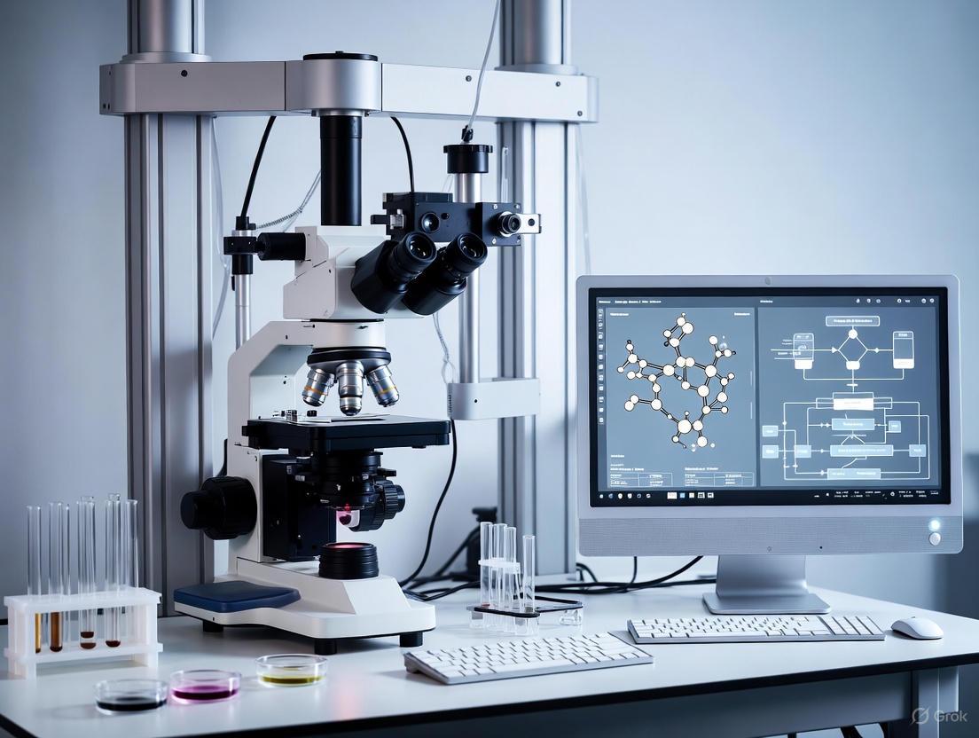
Laser Microsurgery with Real-Time OCT Guidance: Principles, Applications, and Future Directions for Biomedical Research
This article comprehensively reviews the rapidly evolving field of laser microsurgery integrated with real-time Optical Coherence Tomography (OCT) guidance.
Laser Microsurgery with Real-Time OCT Guidance: Principles, Applications, and Future Directions for Biomedical Research
Abstract
This article comprehensively reviews the rapidly evolving field of laser microsurgery integrated with real-time Optical Coherence Tomography (OCT) guidance. Tailored for researchers, scientists, and drug development professionals, we explore the foundational principles of OCT technology, from its basic interferometry to advanced functional extensions like OCT angiography. The core of the discussion details innovative methodological implementations, including robotic-OCT systems and their application in diverse settings from ophthalmology to endoscopic procedures. We critically address key challenges in system integration and optimization, such as real-time data processing and precision control, and present a rigorous validation of the technology's efficacy through comparative analyses with conventional methods. Finally, the review synthesizes these insights to outline future trajectories, emphasizing the transformative potential of AI integration and the path toward clinical translation for enhanced surgical precision and therapeutic outcomes.
The Principles of OCT: A Foundation for Real-Time Surgical Guidance
The shift from Time-Domain (TD-OCT) to Fourier-Domain Optical Coherence Tomography (FD-OCT) represents a pivotal technological evolution in biomedical imaging. This transition has been particularly transformative for applications requiring high speed and resolution, such as real-time guidance in laser microsurgery. In Time-Domain OCT, the imaging mechanism involves mechanically scanning a reference mirror to depth-resolve backscattered light from tissue, fundamentally limiting its acquisition speed to a few hundred A-scans per second [1] [2]. The advent of Fourier-Domain techniques eliminated this mechanical bottleneck by using spectrally resolved detection, enabling orders-of-magnitude improvements in sensitivity and speed [1]. This advancement is crucial for intraoperative scenarios, where minimizing motion artifacts and providing instantaneous feedback can significantly impact surgical precision and outcomes.
Technical Comparative Analysis: Time-Domain vs. Fourier-Domain OCT
Fundamental Operating Principles
The core distinction between Time-Domain and Fourier-Domain OCT lies in their signal acquisition and processing methodologies:
- Time-Domain OCT (TD-OCT): This original OCT technology utilizes a broadband light source and a scanning reference mirror within a Michelson interferometer setup. The interference signal is detected sequentially in time as the mirror moves, building an A-scan point-by-point. This mechanical scanning inherently limits imaging speed and introduces stability concerns [1] [2].
- Fourier-Domain OCT (FD-OCT): FD-OCT captures the entire depth profile simultaneously by measuring the interferometric signal as a function of optical wavenumber. The depth-resolved structural information is then obtained via a Fourier transform. FD-OCT is implemented in two primary configurations, both offering superior performance over TD-OCT [1]:
Quantitative Performance Comparison
The table below summarizes the key performance metrics that underscore the advantages of FD-OCT for high-speed applications like laser microsurgery guidance.
Table 1: Performance Comparison between Time-Domain and Fourier-Domain OCT Systems
| Performance Metric | Time-Domain OCT | Fourier-Domain OCT | Implication for Laser Microsurgery |
|---|---|---|---|
| Imaging Speed | 400 A-scans/second [2] | 16,000–100,000+ A-scans/second [1] [3] | Enables real-time volumetric imaging and tracking of surgical tools and tissue effects. |
| Axial Resolution | 8–10 μm [2] | 3–8 μm [2] [3] | Finer detail resolution improves identification of tissue layers and precise ablation depth control. |
| Detection Sensitivity | Standard (Baseline) | 50–100x improvement over TD-OCT [1] | Higher signal-to-noise ratio allows for faster scanning speeds or lower light exposure. |
| Key Limitation | Mechanical scanning limit | Spectrometer readout (SD-OCT) or laser sweep rate (SS-OCT) | - |
The dramatic increase in FD-OCT speed is a critical enabler for clinical workflows. For example, in cardiology, high-speed FD-OCT allows long coronary artery segments to be imaged following a brief saline flush, a procedure that was not feasible with slower TD-OCT systems [1]. This principle directly translates to microsurgery, where rapid 3D data acquisition is essential for dynamic guidance.
Experimental Protocols for FD-OCT in Laser Microsurgery
Protocol for Real-Time Coagulation Depth Monitoring
The following protocol, adapted from studies on real-time OCT surveillance of laser therapy, details the setup and procedure for monitoring thermal coagulation depth—a critical parameter in many laser microsurgery procedures [4].
Objective: To monitor and control laser-induced tissue coagulation in real-time, automatically terminating the therapy laser when a pre-defined treatment depth is reached.
Materials and Reagents:
- FD-OCT system (Spectral-Domain or Swept-Source)
- Therapy laser (e.g., diode laser) with computer-controlled trigger
- Double-Clad Fiber (DCF) coupler and single DCF catheter
- Tissue sample (e.g., ex vivo rat tissue)
- Data acquisition and real-time processing computer
Procedure:
- System Integration: Combine the OCT imaging beam and therapy laser into a single, co-registered DCF using a double-clad fiber coupler. This ensures perfect spatial alignment between the imaging and treatment spots [4].
- Sample Preparation: Mount the tissue sample securely. For motion correction validation, a motorized stage can be used to introduce controlled bulk motion.
- Baseline Acquisition: Acquire a sequence of OCT B-scans at the target location prior to laser activation to establish baseline speckle patterns.
- Initiate Therapy and Monitoring:
- Start the therapy laser at predefined parameters (wavelength, power).
- Simultaneously, acquire consecutive OCT B-scans at the same location.
- Real-Time Speckle Decorrelation Analysis:
- Calculate the inter-frame speckle intensity decorrelation within a rolling time window. Tissue coagulation alters the scattering properties, causing a transient increase in speckle decorrelation. Fully coagulated tissue returns to a more static speckle pattern [4].
- Apply noise and motion correction algorithms to the decorrelation data to improve accuracy and robustness [4].
- Depth Estimation and Feedback Control: In real-time, identify the depth at which the correlation coefficient indicates active coagulation. When this depth reaches the user-defined target, the processing software sends a stop signal to the therapy laser driver.
Applications: This protocol is suitable for precise ablation in epithelial tissues, such as in treatments for Barrett's esophagus or retinal photocoagulation, where avoiding over- or under-treatment is critical [4].
Protocol for Robotic-OCT Guided Inspection and Microsurgery
This protocol outlines the use of a robotic-arm-integrated FD-OCT system for non-destructive inspection and precise laser ablation, a methodology with direct relevance to microsurgical procedures [5].
Objective: To perform automated, high-resolution volumetric imaging and subsequent OCT-guided microsurgery on a sample with high precision.
Materials and Reagents:
- Spectral-Domain OCT system integrated with a multi-axis robotic arm
- Galvano-scanner for fast-axis OCT scanning
- Ablation laser (e.g., femtosecond laser) integrated into the system
- Sample (e.g., monolithic storage device or biological tissue)
Procedure:
- System Calibration: Precisely calibrate the coordinate transformation between the OCT scanner, the robotic arm end-effector, and the ablation laser path.
- Continuous Volumetric Scanning:
- Program the robotic arm to follow a continuous scanning trajectory over the area of interest, avoiding a stop-and-stare approach.
- During the robotic arm's movement, the OCT system continuously acquires B-scans. This strategy enables rapid acquisition of large volumetric datasets (e.g., imaging a micro-SD card in ~37 seconds) [5].
- 3D Reconstruction and Target Identification:
- Reconstruct a 3D OCT volume from the acquired data.
- Generate en face projections and cross-sectional views to identify subsurface targets (e.g., specific circuit traces or tissue structures).
- Surgical Planning: Based on the 3D reconstruction, define the coordinates and boundaries for the ablation procedure within the software.
- Robotic-OCT Guided Ablation:
- The robotic arm automatically positions the ablation laser focus at the first target coordinate.
- The laser is activated to remove material with micron-scale precision.
- The process repeats for all planned targets, achieving an ablation positioning accuracy of ~50 μm [5].
Applications: This protocol enables highly precise, image-guided removal of specific layers or structures, applicable from industrial reverse engineering to delicate surgical dissection in biological tissues [5].
The Scientist's Toolkit: Key Research Reagent Solutions
Table 2: Essential Materials and Components for FD-OCT Guided Microsurgery Research
| Item | Function/Description | Example Use Case |
|---|---|---|
| Double-Clad Fiber (DCF) Coupler | Combines OCT imaging light (single-mode core) and therapy laser (multi-mode inner cladding) into one fiber for perfect coregistration [4]. | Enables single-fiber catheters/endoscopes for co-localized imaging and therapy. |
| Wavelength-Swept Laser | The light source for SS-OCT. Key specs: sweep rate (kHz), tuning range (nm), and output power. Newer lasers achieve 200+ kHz rates [1] [6]. | Provides the high A-scan rate needed for real-time 4D (3D + time) imaging during procedures. |
| High-Speed 2D Camera | The detector in SD-OCT systems (line-scan camera) or LF-FD-OCT systems (area-scan camera). Speed and pixel count directly determine imaging performance [1] [3]. | Critical for achieving high-volume acquisition rates in SD-OCT and parallel detection in Line-Field OCT. |
| Galvano-Scanner | Provides fast, precise deflection of the imaging beam for lateral scanning. A single-axis scanner is sufficient for LF-FD-OCT B-scan acquisition [3]. | Enables rapid 2D and 3D scanning. MEMS scanners offer a compact alternative for miniaturized probes. |
| Speckle Decorrelation Algorithm | A processing method that quantifies temporal changes in OCT speckle pattern to monitor dynamic processes like blood flow or tissue coagulation [4]. | Serves as the feedback signal for real-time monitoring of laser thermal therapy depth. |
Workflow and System Diagrams
In laser microsurgery, the integration of real-time Optical Coherence Tomography (OCT) guidance has emerged as a transformative approach for enhancing precision, enabling non-invasive visualization of subsurface tissue structures during therapeutic procedures. The efficacy of these integrated systems is fundamentally governed by three core performance metrics: resolution (the ability to distinguish fine spatial features), penetration depth (the maximum depth at which useful signals can be obtained), and imaging speed (the rate of data acquisition critical for real-time feedback). This document provides detailed application notes and experimental protocols for quantifying these metrics, framed within the context of advancing laser microsurgery with real-time OCT guidance for researchers, scientists, and drug development professionals.
Quantitative Performance Metrics Table
The following table summarizes the typical and advanced performance ranges for key OCT metrics, as reported in recent literature.
Table 1: Key Performance Metrics for OCT in Guided Laser Microsurgery
| Performance Metric | Typical Range (Standard Systems) | Advanced/Recent Demonstrations | Key Enabling Technology/Method | Reference(s) |
|---|---|---|---|---|
| Axial Resolution | 1 - 15 µm | ~2.8 µm (in air)~8 µm (in tissue) | Broadband sources (110 nm bandwidth at 840 nm); FDML lasers (100-110 nm bandwidth at 1300 nm) | [7] [8] |
| Lateral Resolution | 10 - 20 µm | ~15 µm~7 µm (with robotic arm) | 4x Objective Lens; Custom OCT probes with galvo scanners and robotic positioning | [7] [9] |
| Penetration Depth | 1 - 2 mm in skin | Significantly improved with topical dyes~5 mm imaging range (MHz-OCT) | Topical application of absorbing dyes (e.g., Tartrazine, 4-Aminoantipyrine); FDML lasers at 1300 nm | [4] [7] [8] |
| Imaging Speed (A-scan rate) | 10 - 400 kHz | 3.3 MHz (A-scan rate)667 Hz (Frame rate) | Fourier Domain Mode Locking (FDML) lasers with optical buffering | [8] |
| Data Acquisition Time | Tens of minutes (stop-and-stare scanning) | ~37 seconds for a micro-SD card volumetric scan | Robotic-arm-assisted continuous scanning strategy | [9] |
Experimental Protocols for Performance Validation
Protocol for Quantifying Resolution
Objective: To empirically measure the axial and lateral resolution of an OCT system.
Materials:
- OCT system under test.
- United States Air Force (USAF) 1951 resolution test target.
- Mirror or a highly reflective, flat surface.
- Index-matching fluid (if necessary).
Procedure:
- Axial Resolution Measurement:
- Place the mirror in the sample arm, ensuring the surface is perpendicular to the beam.
- Acquire an A-scan signal from the mirror.
- The axial resolution is defined as the full width at half maximum (FWHM) of the point spread function (PSF) in the depth direction. This can be obtained directly from the A-scan peak.
- Note: The theoretical axial resolution is given by ∆𝑧 = (2 ln 2 / π) • (λ² / ∆λ), where λ is the central wavelength and ∆λ is the FWHM spectral bandwidth of the source [8].
- Lateral Resolution Measurement:
- Place the USAF 1951 target in the sample arm.
- Acquire a cross-sectional (B-scan) or en face image of the target.
- Identify the smallest group of elements where the lines can be clearly distinguished. The lateral resolution corresponds to the line width (in µm) of that group.
- Alternatively, perform a knife-edge test or measure the FWHM of the beam profile.
Protocol for Assessing Penetration Depth
Objective: To determine the maximum depth at which structures can be clearly visualized in a scattering sample.
Materials:
- OCT system.
- Sample of interest (e.g., ex vivo tissue model, tissue phantom with known optical properties).
- (Optional) Optical clearing agents (e.g., Tartrazine, 4-Aminoantipyrine gel) [7].
Procedure:
- Prepare the sample according to standard procedures (e.g., shaving and cleaning for skin imaging).
- Acquire a cross-sectional OCT image (B-scan) of the untreated sample.
- Penetration Depth Analysis:
- Identify a region in the image with uniform structure.
- Plot the average signal intensity as a function of depth.
- The penetration depth is typically defined as the depth at which the signal intensity drops to 1/e² (about 13.5%) of its value at the surface or to the noise floor of the system.
- (Optional) With Optical Clearing:
- Topically apply an absorbing dye gel (e.g., 38% w/w 4-Aminoantipyrine in agarose gel) to the sample surface for 10-15 minutes [7].
- Acquire a new B-scan image from the same region.
- Quantify the new penetration depth and compare it with the baseline measurement.
Protocol for Evaluating Imaging Speed and Data Acquisition
Objective: To verify the system's A-scan rate, frame rate, and the efficiency of volumetric scanning.
Materials:
- OCT system with known theoretical A-scan rate.
- Computer with software for data acquisition and processing time analysis.
- Sample or target for imaging.
Procedure:
- A-scan and Frame Rate Verification:
- Check the system specifications for the laser A-scan rate (e.g., 3.3 MHz for an FDML laser [8]).
- The B-scan frame rate is calculated as (A-scan rate) / (number of A-scans per B-scan). For example, with 3000 A-scans per B-scan at 3.3 MHz, the frame rate is approximately 1100 Hz.
- Empirically confirm this by timing the acquisition of a set number of B-scans.
- Volumetric Scanning Efficiency:
- Compare scanning strategies using a standardized sample (e.g., a micro-SD card [9]).
- Stop-and-Stare Scanning: Program the robotic arm to move to discrete points, pausing at each to acquire a B-scan. Record the total time to cover a defined area.
- Continuous Scanning: Program the robotic arm to move the OCT probe continuously while it acquires B-scans. Record the total time to cover the same area.
- Calculate the time saving achieved by the continuous scanning strategy.
The Scientist's Toolkit: Essential Research Reagents & Materials
Table 2: Key Research Reagent Solutions for OCT-Guided Laser Microsurgery
| Item / Reagent | Function / Application | Example Use Case / Note |
|---|---|---|
| Double-Clad Fiber (DCF) & Coupler | Enables co-registered OCT imaging and laser therapy through a single fiber; core for OCT, inner cladding for therapy laser. | Critical for miniaturized, integrated endoscopic systems for perfectly overlayed imaging and treatment [4]. |
| Absorbing Dye Molecules(e.g., Tartrazine, 4-Aminoantipyrine) | Act as optical clearing agents (OCAs). Increase refractive index of aqueous tissue components, reducing scattering and enhancing penetration depth. | Topically applied as a gel with agarose and PBS. FDA-approved food dyes like Tartrazine offer a potentially safe profile for in vivo use [7]. |
| Continuous-Wave Laser Diodes (CW-LDs)(e.g., 450 nm, 532 nm) | Used as the therapeutic laser for procedures like coagulation. Chosen for high absorption by specific chromophores (e.g., hemoglobin). | A cost-effective alternative to pulsed lasers. 450 nm light has a higher extinction coefficient for hemoglobin, leading to efficient coagulation [10]. |
| Fourier Domain Mode Locked (FDML) Laser | A high-speed laser source that enables MHz-rate OCT imaging, facilitating real-time 3D visualization. | Essential for acquiring large fields of view without motion artifacts, a cornerstone for real-time surgical guidance [8]. |
| Robotic Arm Integration | Provides precise, automated positioning of the OCT probe or laser. Enables continuous scanning for fast, large-area volumetric imaging. | Improves repeatability, eliminates manual intervention, and significantly reduces data acquisition time [9]. |
System Integration and Workflow Diagram
The following diagram illustrates the core operational workflow and component integration for a typical OCT-guided laser microsurgery system.
Figure 1: Workflow for OCT-guided laser microsurgery. This diagram outlines the closed-loop process of using real-time OCT for target identification, guided laser application, and continuous monitoring until the therapeutic endpoint is achieved.
The advancement of laser microsurgery is intrinsically linked to improvements in OCT guidance, which in turn relies on a critical understanding of resolution, penetration depth, and imaging speed. The protocols and metrics outlined herein provide a framework for researchers to systematically evaluate and optimize these parameters. The integration of advanced technologies such as MHz-speed FDML lasers, robotic positioning, and novel optical clearing agents is pushing the boundaries of what is possible, paving the way for more precise, efficient, and non-invasive surgical interventions.
The integration of functional optical coherence tomography (OCT) extensions, particularly OCT angiography (OCTA) and polarization-sensitive OCT (PS-OCT), is transforming the landscape of image-guided laser microsurgery. These technologies provide complementary intraoperative data streams: OCTA delivers real-time, high-resolution maps of vascular perfusion down to the capillary level, while PS-OCT quantitatively assesses tissue birefringence properties to identify structured collagen in connective tissues and detect thermal damage. This application note details the operating principles, quantitative benchmarks, and practical implementation protocols for integrating OCTA and PS-OCT into laser microsurgery research, providing a framework for enhancing surgical precision and monitoring therapeutic outcomes in real time.
In laser microsurgery, the precise delineation of target tissues and the immediate evaluation of laser-tissue interaction are critical. Traditional intensity-based OCT provides structural information but lacks specific contrast to differentiate critical microstructures. Functional OCT extensions address this limitation by exploiting additional properties of light.
- OCTA utilizes motion contrast from flowing blood cells to generate detailed vascular maps without exogenous dyes. In laser microsurgery, this enables precise targeting of blood vessels for coagulation and immediate verification of vascular occlusion [10] [11].
- PS-OCT measures changes in the polarization state of backscattered light, which is sensitive to the birefringent properties of tissues like tendon, muscle, and corneal stroma. This allows researchers to monitor the disruption of organized collagen matrices during laser ablation and assess the extent of thermal damage in real time [12] [13] [14].
The synergy of these modalities provides a comprehensive intraoperative imaging suite. For instance, an integrated OCT-guided laser microsurgery system can use OCTA to confirm the occlusion of a target vessel while simultaneously using PS-OCT to ensure the surrounding birefringent connective tissue is spared from collateral thermal damage [10] [12].
Quantitative Performance Data
The following tables summarize key performance metrics for OCTA and PS-OCT technologies, which are essential for selecting appropriate systems and protocols for laser microsurgery applications.
Table 1: Key Performance Metrics for OCTA Technologies
| Technology | Contrast Mechanism | Key Performance Metric | Value | Relevance to Laser Microsurgery |
|---|---|---|---|---|
| DOCT (Phase-Resolved) [15] | Phase shift between A-scans | Minimum measurable velocity (v_min) | ( v{min} = \frac{\lambda0}{2\pi \sqrt{2} n T \cos\theta} \frac{1}{\sqrt{SNR}} ) | High sensitivity to slow flow in capillaries; can be saturated by fast flow. |
| Amplitude-Decorrelation (SSADA) [16] | Intensity variance between B-scans | Improves vessel continuity and contrast | Used for split-spectrum methods | Robust to phase noise; excellent for capillary network visualization. |
| OMAG [16] [12] | Complex signal difference (amplitude & phase) | Combined flow sensitivity | Higher contrast than amplitude or phase alone | Enhanced visualization of microvasculature permeating tissue. |
| SC-OCTA [17] | Spectral absorption/scattering of hemoglobin | Enables angiography from a single scan | Acquisition time: ~4.5 seconds | Eliminates motion artifacts; can image non-flowing blood (e.g., post-coagulation). |
Table 2: Key Performance Metrics for PS-OCT Technologies
| Parameter | Technology/Method | Typical Value/Outcome | Application Context |
|---|---|---|---|
| Birefringence Measurement | Jones Matrix/Stokes Vector analysis [13] | Quantifies phase retardation and axis orientation | Differentiates tendon, corneal stroma, retinal nerve fiber layer (RNFL). |
| System Configuration | Dual-Channel (H & V) PS-OCTA [12] | Eliminates polarization-induced artifacts in OCTA | Ensures accurate vascular imaging in birefringent tissues like skin. |
| Data Processing | Contrastive Unpaired Translation (CUT) [18] | Generates synthetic PS-OCT from OCT; classification accuracy up to 90.13% | Reduces data acquisition needs; useful for pre-surgical planning. |
| Blood Flow Sensitivity | PS-OCTA integrated system [12] | Capillary flow sensitivity (0.1–0.9 mm/s in human skin) | Critical for monitoring microcirculation during procedures. |
Experimental Protocols for Laser Microsurgery
Protocol for OCTA-Guided Laser Coagulation
This protocol is adapted from studies demonstrating successful induction of hemostasis in mouse models [10].
1. System Setup and Calibration
- Integrated System: Combine a spectral-domain OCT system with a continuous-wave laser diode (CW-LD). Visible wavelengths (e.g., 450 nm or 532 nm) are preferred due to the high absorption coefficients of oxy- and deoxy-hemoglobin [10].
- Laser Parameters: Use a 450 nm or 532 nm CW-LD with an output power of ~50 mW (adjustable). The laser beam must be co-axial with the OCT scanning beam.
- OCTA Imaging: Employ a repeated B-scan protocol (e.g., 5-8 repetitions per location) and compute decorrelation using an amplitude- or complex-signal-based algorithm (e.g., OMAG) to generate the angiogram [16] [12].
2. Target Identification and Positioning
- Acquire a 3D OCTA scan of the surgical field (e.g., mouse ear skin or omentum).
- Use the OCTA en face projection and cross-sectional B-scans to identify the target vessel.
- Implement an image-based feedback positioning algorithm. The system software calculates the spatial coordinates of the target (e.g., a site of blood leakage) and automatically positions the therapeutic laser beam at its center [10].
3. Laser Coagulation and Real-Time Monitoring
- Initiate Exposure: Activate the CW-LD for controlled intervals (e.g., 3-21 seconds).
- Monitor with OCT/OCTA: Acquire sequential OCT B-scans at the target location during and between exposure intervals.
- Endpoint Determination: Coagulation is confirmed by observing two key changes in the OCT/OCTA data:
- Structural (OCT): Shrinking and increased backscattering of the blood clot.
- Vascular (OCTA): A significant increase in cross-correlation coefficients at the exposure site, indicating the cessation of blood cell movement and successful coagulation [10].
OCTA-guided laser coagulation workflow: a closed-loop system for precise vessel targeting and endpoint confirmation.
Protocol for PS-OCT Monitoring of Collagen Thermal Alteration
This protocol is designed to monitor changes in tissue birefringence, indicative of collagen denaturation, during laser procedures [12] [18].
1. System Setup
- PS-OCT System: Utilize a swept-source PS-OCT system with a dual-channel detection unit (horizontal and vertical polarization channels). A system centered at 1310 nm is suitable for deeper tissue penetration in dermatological or tendon applications [12].
- Calibration: Ensure the polarization controllers and waveplates in the system are properly aligned. The reference arm quarter-waveplate should be set at 22.5° to the input polarization state [12].
2. Data Acquisition and Processing
- Pre-operative Baseline: Acquire a 3D PS-OCT dataset of the target tissue (e.g., tendon). Calculate the phase retardation map and en face projection of the birefringence.
- Real-Time Imaging During Laser Exposure: Continuously acquire and process B-scans at the laser impact site.
- Birefringence Analysis: For each channel (H and V), compute the Stokes parameters (I, Q, U, V) and then derive the phase retardation (δ) using: ( \delta = \frac{1}{2} \arctan\left(\frac{U}{Q}\right) ) [13].
- The cumulative phase retardation can be visualized as a color-encoded image, where hue represents the optic axis orientation and intensity represents the magnitude of retardation [12].
3. Interpretation of Thermal Effects
- Healthy Tissue: Appears with strong, regular periodic banding patterns in the phase retardation B-scan, indicating well-organized, native collagen fibrils [18].
- Thermal Damage/Denaturation: Manifests as a localized reduction or loss of birefringence and a disruption of the regular banding pattern. This occurs because the heat from the laser disrupts the highly ordered structure of collagen, destroying its form birefringence [18].
The Scientist's Toolkit: Research Reagent Solutions
Table 3: Essential Research Materials for OCTA/PS-OCT Laser Microsurgery Studies
| Item | Function/Description | Example Use Case |
|---|---|---|
| Visible CW Laser Diodes (450 nm, 532 nm) | Therapeutic laser; high absorption by hemoglobin enables efficient photocoagulation. | Inducing blood coagulation in vessel phantoms or in vivo models [10]. |
| Mouse Model (e.g., Ear Skin) | In vivo model with translucent tissue and easily accessible vasculature. | Testing and optimizing OCTA-guided coagulation protocols [10]. |
| Achilles Tendon Injury Mouse Model | Model for tissue regeneration with defined birefringence changes. | Monitoring collagen reorganization during healing post-laser surgery with PS-OCT [18]. |
| Intralipid Phantom with Capillary Tube | Tissue-mimicking phantom with controlled flow for system validation. | Calibrating Doppler OCT flow measurements and OCTA signal vs. flow velocity [15] [17]. |
| Polarization Controller & PM Fibers | Controls and maintains the polarization state of light in the interferometer. | Essential for building a stable and accurate fiber-based PS-OCT system [12]. |
| CUT (Contrastive Unpaired Translation) Model | Deep learning model generating synthetic PS-OCT from intensity OCT. | Pre-surgical prediction of birefringence patterns and data augmentation [18]. |
System Integration Diagram
A schematic of a proposed integrated setup for PS-OCTA-guided laser microsurgery is provided below. This dual-functional system is capable of providing artifact-free vascular imaging and birefringence contrast simultaneously [12].
Integrated PS-OCTA system schematic: dual-channel detection enables simultaneous microvascular and birefringence imaging.
Optical Coherence Tomography (OCT) fulfills a critical role in advanced laser microsurgery by providing non-invasive, high-resolution, depth-resolved imaging capabilities that were previously unattainable with other intraoperative technologies. As a non-invasive interferometric technique, OCT generates micron-level cross-sectional or three-dimensional images of biological tissue microstructures in near real-time, functioning as a type of optical biopsy without requiring physical tissue removal [19] [20]. This capability is particularly valuable in laser microsurgery contexts where precise subsurface visualization is essential for accurate treatment but traditional microscopic tissue diagnosis via biopsy is either unavailable or undesirable [21].
The fundamental value proposition of OCT lies in its unique combination of key characteristics: non-invasiveness (no tissue contact or removal required), high resolution (typically 1-15 μm axial resolution), depth-sectioning capability (penetration depth of 1-2 mm in tissue), and real-time imaging performance (video-rate acquisition) [4] [20]. These attributes enable surgeons to visualize subsurface tissue layers during procedures, monitor therapeutic effects as they occur, and guide laser interventions with unprecedented precision, ultimately improving safety and efficacy outcomes across various surgical specialties including ophthalmology, dermatology, and oncology.
Technical Foundations of OCT Imaging
Basic Principles and Methodologies
OCT operates on the principle of low-coherence interferometry to measure the echo time delay and magnitude of backscattered or back-reflected light from tissue microstructures [21] [20]. The technique is often compared to ultrasound imaging due to similar working principles, but uses light waves in the near-infrared spectral range instead of sound waves [21]. In typical OCT configurations, light from a source is split into two paths - a reference arm and a sample arm. The reflected light from both arms is optically recombined, and interference is measured to reveal depth information about reflection sites within the sample [22]. This process generates depth-resolved profiles known as A-scans (amplitude scans), while cross-sectional images (B-scans) are created by scanning the beam laterally across the sample [21].
Table 1: Comparison of Primary OCT Detection Methods
| Parameter | Time-Domain OCT (TD-OCT) | Spectral-Domain OCT (SD-OCT) | Swept-Source OCT (SS-OCT) |
|---|---|---|---|
| Fundamental Principle | Mechanical scanning of reference mirror depth | Spectrometer with line-scan camera detects spectral interference | Laser source sweeps wavelengths rapidly while detector measures interference |
| Axial Resolution | 10-15 μm | 5-7 μm | 5-7 μm |
| Imaging Speed | Slow (hundreds to thousands of A-scans/sec) | Fast (tens to hundreds of thousands of A-scans/sec) | Very fast (hundreds of thousands to millions of A-scans/sec) |
| Signal-to-Noise Ratio | Lower | Higher than TD-OCT by factor proportional to detector pixels | Similar to SD-OCT, high |
| Advantages | Simpler concept, constant sensitivity with depth | Faster imaging, better SNR | Highest speed, long imaging range potential |
| Disadvantages | Limited speed, mechanical moving parts | Sensitivity decreases with depth | Higher cost, complex laser source required |
| Primary Applications | Early-generation systems | Retinal imaging, general biomedical applications | High-speed volumetric imaging, long-range imaging |
Wavelength Considerations for Tissue Imaging
The selection of operational wavelength significantly influences OCT imaging performance, particularly regarding penetration depth and contrast. While early ophthalmic OCT systems operated at 800 nm, longer wavelengths in the 1050 nm and 1300 nm bands were subsequently introduced to achieve improved imaging depth [23] [20]. The general trend for tissue scattering coefficients is to decrease with increasing wavelength, making longer wavelengths potentially more advantageous for deeper imaging. However, this advantage is constrained by increased optical absorption of water at longer wavelengths [23]. Recent investigations into the 1600-1800 nm spectral window between primary water absorption bands have demonstrated enhanced imaging depth compared to 1300 nm for certain tissue types, with improvements reaching up to 30% for highly scattering samples [23].
OCT-Guided Laser Microsurgery: Experimental Protocols
Real-Time Monitoring of Laser Coagulation
Objective: To monitor and control laser-induced tissue coagulation in real-time using OCT guidance, automatically terminating therapy when targeted coagulation depth is achieved.
Materials and Equipment:
- Spectral-domain or swept-source OCT system
- Therapy laser (continuous-wave or pulsed)
- Double-clad fiber coupler (DCFC) and double-clad fiber (DCF) for co-registered imaging and therapy
- Computer system with real-time processing capability
- Tissue sample (ex vivo or in vivo)
Methodology:
- System Configuration: Integrate OCT imaging and therapy lasers using a double-clad fiber coupler to ensure perfect co-registration of imaging and treatment beams [4].
- Baseline Imaging: Acquire reference OCT B-scans of the target tissue region before therapy initiation.
- Laser Therapy Initiation: Begin laser therapy at predetermined parameters (wavelength, power, spot size).
- Real-time Speckle Decorrelation Analysis:
- Calculate intensity correlation of OCT speckle patterns during coagulation process
- Apply noise correction to extend maximum monitoring depth
- Implement motion correction to compensate for tissue movement [4]
- Coagulation Depth Tracking: Monitor the temporal evolution of speckle correlation to identify the transition boundary between coagulated and non-coagulated tissue.
- Automated Termination: Program system to automatically shut off therapy laser when the calculated coagulation depth reaches the predetermined target depth (e.g., 500-1000 μm) [4].
Validation: Confirm coagulation depth and extent through histological analysis of tissue samples following the procedure.
Blood Coagulation Monitoring with OCT Angiography
Objective: To induce and monitor blood coagulation using visible laser diodes under OCT guidance, with validation through angiography.
Materials and Equipment:
- Spectral-domain OCT system with angiography capability
- Continuous-wave laser diodes (450 nm and 532 nm wavelengths)
- Animal model (e.g., mouse ear)
- Precision positioning system
- Image processing software for correlation analysis
Methodology:
- Vessel Preparation: Induce blood leakage by puncturing target vessel with micro-needle.
- 3D OCT Baseline: Acquire 3D microstructural images and calculate cross-correlation coefficients for baseline angiography [10].
- Laser Positioning: Use image-based feedback positioning to accurately direct therapy laser to target location.
- Coagulation Therapy: Apply laser exposure at predetermined parameters (e.g., 3-21 second exposures).
- Time-Series Imaging: Capture OCT images at regular intervals during laser exposure to monitor coagulation progression.
- Angiographic Analysis: Calculate cross-correlation coefficients between successive OCT B-scans to visualize blood flow changes.
- Quantitative Assessment: Measure changes in blood drop area over time to quantify coagulation efficiency [10].
Table 2: Blood Coagulation Parameters with Different Laser Wavelengths
| Laser Parameter | 450 nm Laser Diode | 532 nm Laser Diode |
|---|---|---|
| Absorption Characteristics | Higher extinction coefficient for both oxyhemoglobin and deoxyhemoglobin | High absorption for oxyhemoglobin |
| Time to Initial Coagulation | ≤3 seconds | ≤3 seconds |
| Coagulation Efficiency | More efficient at same power level | Slightly less efficient than 450 nm |
| Observation | Blood drop area decreases with exposure time | Blood clot formation observed after ~9 seconds |
| Advantages | Superior coagulation efficiency | Good balance of penetration and absorption |
Advanced Integration: Robotic OCT Systems
The integration of OCT with robotic systems has created new possibilities for precise laser microsurgery applications. Robotic OCT configurations can be classified into four main categories based on the geometric relationship between the robot and imaging system [19]:
- Robot-Adjacent OCT: Tabletop OCT system provides imaging feedback to a robot manipulator holding surgical instruments [19].
- Robot-Mounted OCT: OCT system mounted directly to robot end-effector for coordinated movement [19].
- Robot-Guided OCT Sensing Tools: Robot delivers specialized OCT sensing tools to target locations [19].
- Endoscopic OCT: Miniaturized OCT systems integrated into endoscopic platforms for internal procedures [19].
These configurations enable previously challenging applications such as large-area tissue scanning, precise tool tracking, and image-guided robotic surgery with real-time volumetric perception beyond the capabilities of conventional camera-based systems [19].
The Scientist's Toolkit: Essential Research Reagents and Materials
Table 3: Essential Research Materials for OCT-Guided Laser Microsurgery Studies
| Item | Function/Application | Examples/Specifications |
|---|---|---|
| OCT System Types | Provides cross-sectional tissue imaging | Spectral-domain OCT, Swept-source OCT [22] |
| Therapy Lasers | Induces photocoagulation or tissue ablation | Continuous-wave laser diodes (450 nm, 532 nm) [10] |
| Double-Clad Fiber Couplers | Enables co-registered imaging and therapy through single fiber | Combines OCT imaging and therapy laser delivery [4] |
| Animal Models | In vivo testing of procedures | Mouse ear models for angiogenesis studies [10] |
| Tissue Phantoms | System validation and calibration | Intralipid solutions at various concentrations [23] |
| Motion Tracking Systems | Compensates for tissue movement during procedures | Scanning laser ophthalmoscope for retinal tracking [21] |
| Speckle Analysis Software | Quantifies tissue changes during coagulation | Custom algorithms for intensity decorrelation calculation [4] |
Emerging Applications and Future Directions
Recent advances in OCT technology have expanded its potential applications in laser microsurgery. Functional OCT techniques now enable non-invasive, depth-resolved imaging of physiological parameters including blood flow, birefringence, and metabolic properties [20]. Doppler OCT and OCT angiography provide visualization of microvascular networks and flow dynamics, particularly valuable for monitoring vascular-targeted therapies [10] [20]. Polarization-sensitive OCT can directly assess thermal damage in birefringent tissues such as muscle and tendon [4].
Long-range SS-OCT systems with extended coherence lengths are emerging as promising platforms for large-volume imaging applications, with recent demonstrations achieving imaging ranges up to 53 meters while maintaining millimeter-level resolution [24]. These systems utilize akinetic all-semiconductor swept lasers with ultra-narrow instantaneous linewidths (<0.6 MHz), enabling theoretical coherence lengths exceeding 200 meters [24]. Such capabilities position OCT as a compelling technology for integration with robotic systems requiring volumetric perception in complex environments.
The combination of these technological advances with laser microsurgical techniques creates new possibilities for precise, image-guided interventions across multiple medical specialties, with ongoing research focused on improving resolution, speed, and functional imaging capabilities to further enhance surgical precision and patient outcomes.
Implementing OCT-Guided Laser Systems: From Laboratory to Clinical Applications
Systems Architecture for Integrated OCT-Laser Platforms
The integration of Optical Coherence Tomography (OCT) with laser microsurgery platforms represents a paradigm shift in precision medicine, enabling real-time visual guidance for surgical interventions. These systems architecturally combine high-resolution, depth-resolved imaging with targeted laser ablation, creating a closed-loop feedback system for unprecedented procedural control.
Core System Components and Integration Principles
Integrated OCT-laser platforms feature a unified architecture where the imaging and therapeutic subsystems share optical pathways and computational infrastructure. The core principle involves using the OCT beam to provide continuous, depth-resolved feedback on tissue microstructure, which then guides the positioning and activation of the surgical laser. This integration occurs through several critical subsystems:
- Common Optical Path: A shared optical system using dichroic mirrors and scanners allows both imaging and therapeutic beams to be co-aligned, ensuring that the surgical area visualized by OCT corresponds precisely with the laser treatment area.
- Real-Time Control System: A centralized processing unit synchronizes data acquisition from the OCT subsystem with command signals to the laser, enabling automated targeting and safety interlocks.
- Robotic Positioning: High-precision robotic arms provide stable, programmable positioning of the integrated toolhead, accommodating various sample sizes and geometries while maintaining optimal focus and orientation [5].
Implementation Architectures
Two predominant architectural implementations have emerged for OCT-guided laser microsurgery:
Multimodal Imaging Platforms: These systems combine OCT with complementary imaging modalities to enhance tissue characterization. For example, the integration of OCT with Photoacoustic Microscopy (PAM) creates a powerful synergistic platform where OCT provides structural information while PAM adds functional vascular imaging without exogenous contrast agents [25]. This dual-modality system has proven particularly valuable in ophthalmology research for monitoring choroidal neovascularization, with lateral spatial resolution of 4.1 μm for PAM and 3.8 μm for OCT at the focal plane [25].
Robotically Assisted Surgical Platforms: These architectures incorporate robotic manipulators for enhanced precision and automation. One demonstrated system achieved lateral resolution of ~7 μm and axial resolution of ~4 μm, with robotic positioning accuracy of ~50 μm and precision of ±10 μm for laser ablation procedures [5]. This system utilized a continuous scanning strategy where a robotic arm moved the OCT probe continuously along the slow axis while the system acquired 3000 B-scans in real-time with a lateral scan range of ~7 mm, significantly faster than traditional stop-and-stare scanning approaches [5].
Table 1: Performance Specifications of Integrated OCT-Laser Systems
| System Parameter | Multimodal OCT-PAM Platform | Robotically Assisted Platform |
|---|---|---|
| OCT Lateral Resolution | 3.8 μm | ~7 μm |
| OCT Axial Resolution | Not specified | ~4 μm |
| Additional Imaging Capabilities | PAM with 4.1 μm resolution | N/A |
| Positioning Accuracy | Not specified | ~50 μm |
| Ablation Precision | Not specified | ±10 μm |
| Scanning Speed | Not specified | 3000 B-scans over 15.5s for 7mm range |
Application Notes: Research and Clinical Implementation
Ophthalmic Microsurgery Guidance
Intraoperative OCT (iOCT) has significantly enhanced surgical feedback in delicate ophthalmic procedures. In the Determination of Feasibility of Intraoperative Spectral Domain Microscope Combined/Integrated OCT Visualization During en Face Retinal and Ophthalmic Surgery (DISCOVER) study, iOCT was shown to alter surgeon decision-making in approximately 40% of corneal transplant cases, with authors concluding that their study showed lower rates of complications and decreased operative time [26]. The technology provides critical axial information that must otherwise be inferred from instrument shadowing and indirect cues when using conventional microscopy alone [25].
For complex procedures such as subretinal injections in research models, real-time OCT guidance has dramatically improved success rates. When performing subretinal injections through a modern microscope without OCT, surgeons are limited to an en face view, but the introduction of iOCT enhances manipulation via visual feedback, refines techniques, and improves success rates for technically challenging procedures that require precise manipulation of delicate tissue on the submillimeter scale [25].
Non-Biological Microsurgery Applications
The integration of OCT guidance with laser ablation has found innovative applications beyond medicine, particularly in data recovery from monolithic storage devices (MSDs). Conventional data recovery methods require manually sanding off the entire insulating layer to expose underlying circuitry, a destructive and imprecise process. The robotic-OCT-guided laser ablation system enables non-destructive inspection and targeted removal of specific areas with precision of ±10 μm and accuracy of ~50 μm, eliminating the need to remove entire layers and significantly improving data recovery efficiency [5].
This system performs automated volumetric imaging of a micro-SD card in approximately 37 seconds, significantly faster than traditional stop-and-stare scanning that typically takes tens of minutes [5]. The architectural approach demonstrates how OCT guidance can transform precision manufacturing and repair processes in electronics and materials science.
Experimental Protocols
Protocol 1: OCT-Guided Subretinal Injection for Choroidal Neovascularization Models
This protocol details the establishment of choroidal neovascularization (CNV) in rabbit eyes using real-time OCT guidance, adapted from published methodology [25] [27].
Research Reagent Solutions
Table 2: Essential Reagents for CNV Model Induction
| Reagent | Specifications | Function |
|---|---|---|
| Matrigel Basement Membrane Matrix | Corning, NY, USA | Forms solid gel at 37°C, trapping growth factors for sustained neovascularization |
| Human VEGF-165 | Shenandoah Biotechnology, Warwick, USA; reconstituted in 1% BSA in sterile water at 0.1 mg/mL stock solution | Potent angiogenic factor inducing blood vessel growth |
| M&V Suspension | 750 ng VEGF (100 μg/mL) in 20 μL Matrigel | Combined formulation for CNV induction |
| Ketamine/Xylazine Mixture | Ketamine (40 mg/kg, 100 mg/mL) and Xylazine (5 mg/kg, 100 mg/mL) | Intramuscular anesthetic for initial sedation |
| Isoflurane Anesthetic | 1 L/min oxygen and 0.75% isoflurane (SurgiVet, MN, USA) | Maintained anesthesia during procedures |
Step-by-Step Procedure
Animal Preparation: Anesthetize New Zealand rabbits (2.5-3.0 kg) with intramuscular ketamine/xylazine mixture. Maintain anesthesia with vaporized isoflurane (1 L/min oxygen, 0.75% isoflurane). Achieve pupillary dilation with one drop each of 1% tropicamide and 2.5% phenylephrine hydrochloride. Apply topical tetracaine 0.5% for corneal anesthesia.
System Configuration: Configure the dual-modality OCT-PAM system with the OCT subsystem adapted from a commercially available spectral-domain OCT system (e.g., Ganymede-Ⅱ-HR, Thorlabs) by adding an ocular lens after the scan lens and dispersion compensation glass in the reference arm.
Surgical Guidance: Position the animal under the integrated imaging system. Use real-time OCT B-scans to guide a subretinal injection cannula. Advance the cannula through the retina under continuous OCT visualization until the tip is confirmed to be in the subretinal space by the appearance of a localized retinal detachment.
Material Injection: Slowly inject 20 μL of the prepared M&V suspension while monitoring for optimal bleb formation via OCT. The cold liquid Matrigel will solidify at body temperature, trapping VEGF and permitting slow release.
Post-procedure Monitoring: Use the dual-modality system to monitor CNV development over time. Typically, CNV and mild tortuosity of small retinal vessels near the injection site appear in all M&V eyes within the study period.
Validation: Confirm CNV formation using both OCT and PAM modalities. OCT provides structural information on retinal layers, while PAM visualizes the neovascular network without exogenous contrast agents by detecting optical absorption properties of hemoglobin.
This protocol has demonstrated 100% success rate in producing CNV in M&V-injected eyes (8/8 eyes) compared to controls injected with sterile water (0/4 eyes showing CNV) [25].
Protocol 2: Robotic-OCT Guided Laser Ablation for Electronic Device Microsurgery
This protocol describes the use of integrated robotic-OCT guidance for precise laser ablation in monolithic storage devices, based on published methodology [5].
System Configuration
Hardware Integration: Mount the OCT probe (with galvo scanner for fast-axis lateral scanning) on a programmable robotic arm for slow-axis lateral scanning. Integrate a laser ablation module with the optical path using dichroic mirrors.
Software Configuration: Implement a continuous scanning strategy where the robotic arm moves continuously while the OCT probe acquires B-scans in real-time. Program the system to automatically fuse en face images of adjacent regions with a 10% overlap to create comprehensive maps of the device.
Calibration: Calibrate the system using reference standards to ensure precise coordination between OCT imaging coordinates and laser targeting coordinates.
Microsurgery Procedure
Device Mounting: Securely mount the MSD (e.g., micro-SD card) in a fixed position relative to the robotic coordinate system.
Volumetric Imaging: Perform automated robotic-OCT scanning with the continuous scanning strategy. For a micro-SD card, this typically involves the robotic arm moving at ~1 mm/s while the OCT system acquires 3000 B-scans over a 15.5 second period for each region, with a lateral scan range of ~7 mm.
Target Identification: Reconstruct 3D volumetric data and identify target areas (e.g., specific conductive traces or pins) through multilayer analysis of the OCT data.
Ablation Planning: Program the robotic system to direct the laser to specific locations identified from OCT data. Set ablation parameters based on the material properties and depth information obtained from OCT.
Precision Ablation: Execute the ablation procedure with the system providing continuous OCT feedback on ablation depth and progress. The system should achieve ablation precision of ±10 μm and accuracy of ~50 μm.
Quality Control: Perform post-ablation OCT imaging to verify complete removal of target material without damage to underlying structures.
Workflow Visualization
Integrated OCT-Laser Microsurgery Workflow
Technical Specifications and Performance Metrics
OCT Subsystem Specifications
Modern integrated platforms utilize spectral-domain OCT (SD-OCT) or swept-source OCT (SS-OCT) technologies. SD-OCT systems typically provide axial resolution of 5-7 μm with scan rates of 20,000-52,000 A-scans/s, while SS-OCT offers improved penetration with scan rates of 100,000-236,000 A-scans/s, though with slightly reduced axial resolution (~11 μm) [28]. These specifications enable rapid volumetric imaging essential for real-time guidance during microsurgical procedures.
Table 3: OCT Technology Comparison for Surgical Guidance
| Feature | Time-Domain OCT (TD-OCT) | Spectral-Domain OCT (SD-OCT) | Swept-Source OCT (SS-OCT) |
|---|---|---|---|
| Light Source | Broadband with moving reference mirror | Broadband with spectrometer | Tunable laser across wavelengths |
| Axial Resolution | 8-10 μm | 5-7 μm | 11 μm |
| Scan Rate | 400 A-scans/s | 20,000-52,000 A-scans/s | 100,000-236,000 A-scans/s |
| Clinical Utility | Basic imaging | Standard for diagnosis/monitoring | Deep tissue and choroidal imaging |
| Guidance Suitability | Limited due to speed | Good for most applications | Excellent for real-time guidance |
Integration and Performance Validation
Successful integration requires rigorous validation of several key performance parameters:
Spatial Registration Accuracy: The positional agreement between OCT-imaged locations and laser-treated locations should be validated using phantom targets with known geometries. The robotic-OCT system demonstrated accuracy of ~50 μm [5].
Temporal Synchronization: The timing between image acquisition, processing, and laser activation must be characterized to ensure guidance reflects tissue state at the moment of treatment.
Ablation Depth Control: The system should be calibrated to correlate OCT signal characteristics with ablation crater dimensions across different tissue types and laser parameters.
Integrated OCT-laser microsurgery platforms represent a significant advancement in precision intervention, with architectures that enable previously impossible procedures in both biological and non-biological domains. The continued refinement of these systems promises to further blur the line between diagnostic imaging and therapeutic intervention across multiple fields of research and clinical practice.
The integration of robotic systems with real-time optical coherence tomography (OCT) guidance represents a transformative advancement in laser microsurgery, creating a closed-loop platform capable of unprecedented surgical precision. This synergy enables subcellular resolution imaging concurrent with robotic intervention, allowing for intraoperative tissue characterization and automated adaptation of surgical maneuvers. Within laser microsurgery, this integration addresses a critical limitation: the inability to visualize underlying tissue structures and monitor surgical effects in real time. Research and clinical protocols are now evolving to leverage OCT's micron-scale resolution (often achieving 1-15 µm) for guiding robotic laser systems, facilitating procedures that are not only minimally invasive but also intelligently automated. This document outlines the application notes and experimental protocols essential for implementing such a system in a research setting focused on laser microsurgery, providing a framework for scientists and drug development professionals to advance therapeutic interventions.
Quantitative Data Synthesis
The following tables summarize key quantitative findings from recent literature on robotic surgery and OCT imaging, highlighting performance metrics and clinical outcomes crucial for evaluating system efficacy.
Table 1: Quantitative Outcomes of AI-Assisted Robotic Surgery versus Manual Techniques
| Performance Metric | AI-Assisted Robotic Surgery | Manual Surgical Techniques | Improvement | Source Context |
|---|---|---|---|---|
| Operative Time | 25% reduction | Baseline | 25% | [29] |
| Intraoperative Complications | 30% decrease | Baseline | 30% | [29] |
| Surgical Precision | 40% improvement | Baseline | 40% | [29] |
| Patient Recovery Time | 15% shortening | Baseline | 15% | [29] |
| Surgeon Workflow Efficiency | 20% increase | Baseline | 20% | [29] |
| Healthcare Costs | 10% reduction | Baseline | 10% | [29] |
Table 2: Key Performance Characteristics of Integrated OCT Imaging
| OCT Feature | Performance Characteristic | Application in Laser Microsurgery | Source Context |
|---|---|---|---|
| Axial Resolution | 1-15 µm (typical) | Enables subsurface tissue differentiation and precise laser targeting. | [30] |
| Imaging Speed | Critical for 4D intraoperative OCT | Allows real-time, volumetric visualization of tissue-instrument interaction. | [30] |
| Functional Extension (OCTA) | Capillary-level visualization | Non-invasive microvasculature mapping; identifies perfusion status. | [30] |
| Visible Light OCT | Enables retinal oximetry | Measures blood oxygen saturation down to the capillary level. | [30] |
| Optoretinography (ORG) | Measures photoreceptor function | Detects stimulus-evoked intrinsic optical signals for functional assessment. | [30] |
Experimental Protocols
Protocol 1: Real-Time OCT Data Acquisition for Robotic Control
This protocol details the setup for capturing real-time OCT image data to inform a robotic control system, a foundational step for automated laser microsurgery.
- Objective: To establish a reliable pipeline for acquiring, processing, and feeding back OCT image data to a surgical robot for real-time guidance.
- Materials:
- Spectral-Domain or Swept-Source OCT engine
- Robotic surgical system (e.g., research-grade da Vinci Xi, custom micro-robot)
- HDMI-to-USB Video Capture Cards (x2 for stereoscopic systems)
- Recording PC with open-source software (OBS Studio)
- Synchronization trigger module
- Procedure:
- System Integration: Physically co-register the OCT imaging probe with the robotic end-effector or laser delivery fiber. Ensure the focal plane of the OCT aligns with the surgical plane of the laser.
- Data Capture Hardware Setup: For robotic systems with video output, connect the endoscopic or auxiliary video signals to the recording PC using HDMI-to-USB video capture cards. This provides a simultaneous view of the surgical field [31].
- Software Configuration: Configure OBS Studio or similar software to record the video stream at a minimum of 15 frames per second (FPS) with a resolution of 1280x720 or higher to ensure sufficient detail for image processing algorithms [31].
- Synchronization: Implement a hardware or software trigger to synchronize the OCT image acquisition with the robotic system's clock. This is critical for correlating imaging data with robotic kinematic data.
- Image Processing Stream: Develop or implement a real-time image processing algorithm to analyze the incoming OCT B-scans or volumes. Key tasks include:
- Segmentation: Identifying and delineating tissue layers (e.g., retinal layers, tumor boundaries).
- Feature Detection: Tracking the position of surgical instruments or the laser focus relative to critical tissue structures.
- Change Detection: Monitoring for laser-induced tissue effects (e.g., bubble formation, changes in scattering).
- Control Loop Closure: Feed the processed image data (e.g., distance to target, detected anomaly) into the robotic controller. The controller should be programmed to adjust the laser's position, power, or pulse duration based on this feedback.
Protocol 2: Validating AI-Driven Surgical Skill Assessment
This protocol leverages AI to objectively assess surgeon proficiency using data captured from a robot-assisted surgical system, which is vital for standardizing training and performance in complex microsurgical tasks.
- Objective: To capture, annotate, and analyze multimodal surgical data (video and kinematics) for automated skill assessment using machine learning.
- Materials:
- Robotic surgical simulator or system (e.g., da Vinci Si/Xi)
- Video capture setup (as in Protocol 1)
- Inertial measurement units (IMUs) or optical trackers for surgeon kinematics
- Annotation software (e.g., CVAT, Label Studio)
- Procedure:
- Participant Grouping: Define two groups of surgeons: novices (<100 procedures) and experienced (>100 procedures) to establish a ground truth for model training [31].
- Multimodal Data Recording:
- Robot Video: Record the endoscopic video stream as described in Protocol 1.
- Kinematic Data: Capture movement data of the surgeon's arms and hands using IMUs or the robotic system's built-in kinematic sensors (e.g., instrument tracking, pedal use) [31].
- Event Data: Extract event data from the robot's video overlay or system logs, including use of cut/coagulation energy, clutch activation, and camera movement [31].
- Data Annotation: Manually annotate the recorded videos frame-by-frame using assessment tools like the Global Evaluative Assessment of Robotic Skills (GEARS). Label specific events, errors, and proficient maneuvers [31].
- AI Model Training: Prepare the annotated dataset (video frames, kinematic traces, event logs) for a machine learning algorithm, such as a convolutional neural network (CNN) combined with a recurrent neural network (RNN). Train the model to predict skill scores based on the input data.
- Validation: Validate the AI model's assessment against scores from expert human raters on a new, unseen set of surgical trials. Metrics like Cohen's Kappa can be used to measure agreement.
System Workflow and Architecture Visualization
Integrated Robotic Surgery with OCT Guidance Workflow
The Scientist's Toolkit: Research Reagent Solutions
Table 3: Essential Research Materials for Robotic-OCT Integration Experiments
| Item / Reagent | Function / Application | Experimental Notes |
|---|---|---|
| Porcine Model Tissues | Ex vivo surgical simulation platform | Provides realistic tissue properties for practicing and validating microsurgical techniques and laser-tissue interaction studies [31]. |
| da Vinci Surgical System (Si/Xi) | Primary robotic surgical platform | Enables research into robotic kinematics, data capture, and integration of external imaging modalities like OCT [31]. |
| Video Capture Cards (HDMI to USB) | Data acquisition hardware | Critical for capturing raw video output from the surgical robot for subsequent AI analysis and real-time processing [31]. |
| Open Broadcaster Software (OBS) | Video recording and streaming software | Open-source solution for synchronously recording multiple video inputs from the robotic and imaging systems [31]. |
| AI/Deep Learning Framework (e.g., PyTorch, TensorFlow) | Algorithm development platform | Used to build and train models for surgical skill assessment, tissue segmentation, and automated surgical guidance [30] [29]. |
| Synchronization Trigger Module | Hardware synchronization | Ensures temporal alignment between OCT image frames and robotic kinematic data, which is essential for closed-loop control [31]. |
| Optical Phantoms | Tissue-simulating materials | Used for system calibration, resolution testing, and simulating the optical properties of human tissue before moving to biological models. |
Intraoperative Optical Coherence Tomography (iOCT) is a transformative imaging modality that provides real-time, cross-sectional tissue visualization during ophthalmic surgery. Unlike conventional surgical microscopes that offer only an en face view, iOCT delivers micron-resolution, depth-resolved images of ocular structures and surgical instruments, enabling unprecedented visualization of subsurface anatomy and tool-tissue interactions [32] [33]. This technology addresses a critical limitation in ophthalmic microsurgery, where the trend toward minimally invasive techniques has outpaced the visualization capabilities of traditional surgical microscopes [32].
The clinical utility of iOCT is well-established across multiple surgical domains. Landmark prospective studies, including the PIONEER and DISCOVER studies, demonstrated that iOCT significantly impacts surgical decision-making, altering surgical strategy in approximately 29-46% of posterior segment surgeries and 46% of anterior segment surgeries [32]. This technology has proven particularly valuable in technically demanding procedures such as lamellar keratoplasty and macular surgery, where precise depth perception is critical for optimal outcomes [32] [34].
For researchers investigating laser microsurgery with real-time OCT guidance, iOCT represents a platform technology that enables precise control of laser-tissue interactions at microscopic scales. The ability to visualize surgical maneuvers in cross-section provides critical feedback for developing closed-loop systems that can automatically adjust laser parameters based on real-time tissue response.
iOCT Technology Platforms and Performance Specifications
iOCT Device Configurations
Three primary iOCT device configurations are currently used in clinical practice, each with distinct advantages and limitations [32]:
- Handheld/Mounted Devices: Early iOCT systems utilized handheld OCT devices that could be mounted to the surgical microscope. While offering flexibility, these systems typically require pausing surgery for image acquisition and present stability challenges during imaging [32].
- Microscope-Integrated OCT (MI-OCT): Fully integrated systems incorporate the OCT directly into the surgical microscope optical path. These systems enable continuous imaging without interrupting surgical workflow and often include heads-up display capabilities for real-time image visualization [32] [33].
- Instrument/Probe Integrated OCT: Emerging systems incorporate OCT technology directly into surgical instruments, enabling imaging of challenging anatomical regions such as the retinal periphery and ciliary body [32].
Technical Specifications of Current iOCT Systems
Modern iOCT systems have evolved significantly from early time-domain implementations to faster Fourier-domain systems, including spectral-domain (SD-OCT) and swept-source (SS-OCT) technologies [21] [33]. The table below summarizes key performance characteristics of current iOCT platforms:
Table 1: Performance Specifications of iOCT Technologies
| Parameter | Spectral-Domain OCT (SD-OCT) | Swept-Source OCT (SS-OCT) |
|---|---|---|
| Scanning Speed | 27,000-70,000 A-scans/second [35] | 100,000-400,000 A-scans/second [33] [35] |
| Axial Resolution | 5-7 μm [35] | ~5.3 μm in tissue [35] |
| Wavelength | 800-870 nm [35] | 1050-1060 nm [33] [35] |
| Penetration Depth | Limited with standard modes; enhanced with EDI [35] | Superior penetration to sclera [35] |
| Real-time Volumetric Imaging | Limited by slower acquisition speeds | Up to 7 volumes/second demonstrated [33] |
Commercially available MI-OCT systems include the Rescan 700 (Carl Zeiss Meditec), OPMedT (Haag-Streit Surgical), and EnFocus (Bioptigen, Leica) [34]. Research-grade systems have achieved even higher performance, with one recent report describing a 400 kHz SS-OCT system capable of real-time 4D visualization at up to 7 volumes per second [33].
Clinical Applications and Quantitative Outcomes
Vitreoretinal Surgery Applications
iOCT provides critical visual feedback during delicate vitreoretinal procedures, enabling surgeons to confirm completion of surgical goals and identify potential complications. The quantitative impact on surgical outcomes is substantial:
Table 2: iOCT Impact on Vitreoretinal Surgical Outcomes
| Application | Key Findings | Impact on Surgical Decision-Making |
|---|---|---|
| Membrane Peeling | Confirms complete removal of epiretinal membranes and identifies residual fragments [32] | Alters surgical approach in 46% of cases [32] |
| Macular Hole Surgery | Visualizes release of vitreomacular traction and confirms complete internal limiting membrane peeling [32] | Guides decision regarding additional membrane dissection [32] |
| Subretinal Injection | Enables precise needle navigation to target depth [36] | Prevents inadvertent RPE damage or under-placement of therapeutic agents [36] |
| Retinal Detachment Repair | Assesses complete retinal reattachment and identifies persistent subretinal fluid [34] | May influence decision to apply additional laser or adjust tamponade [34] |
Anterior Segment Applications
In corneal surgery, iOCT enhances depth perception during technically demanding lamellar procedures, potentially reducing the learning curve for novice surgeons [34]:
Table 3: iOCT Applications in Corneal Surgery
| Procedure | Key Applications | Clinical Benefits |
|---|---|---|
| Deep Anterior Lamellar Keratoplasty (DALK) | Guides needle depth during big bubble technique; visualizes DM separation; detects microperforations [34] | Reduces perforation risk; confirms complete DM separation [34] |
| Descemet Membrane Endothelial Keratoplasty (DMEK) | Assesses graft orientation and unfolding; confirms complete graft attachment [34] | Reduces re-bubbling rates; improves graft survival [34] |
| Penetrating Keratoplasty | Guides suture depth and placement; evaluates wound apposition [34] | Reduces surgically-induced astigmatism; improves wound healing [34] |
| Intracorneal Ring Segment Implantation | Visualizes tunnel depth and relationship to anterior chamber [34] | Prevents perforation; optimizes depth placement [34] |
Impact on Surgical Decision-Making and Workflow
The integration of iOCT into surgical workflow necessitates consideration of its impact on surgical efficiency and cognitive load. Recent research indicates that while iOCT initially increases cognitive load for novice surgeons—evidenced by increased heart rate, heart rate variability, and task completion time—it ultimately enhances depth-related targeting precision [36]. This suggests that with adequate training, surgeons can overcome initial cognitive challenges to achieve superior surgical precision.
Experimental Protocols for iOCT-Guided Laser Microsurgery
Protocol 1: iOCT-Guided Subretinal Injection
This protocol details the experimental setup for precise subretinal injection guidance using iOCT, relevant for gene therapy and stem cell delivery applications.
Materials and Equipment:
- 400 kHz SS-OCT system with real-time volumetric imaging [33]
- Surgical microscope with integrated OCT optics (e.g., Leica Proveo 8 with EnFocus OCT scanner) [33]
- 3D Visualization system (e.g., Alcon NGENUITY) [33]
- Subretinal injection cannula (41-50 gauge)
- Animal model (porcine or primate) or human donor eye
Procedure:
- System Calibration: Align OCT focus with surgical microscope focal plane using motorized stage [33]
- Scan Protocol Selection: Configure anisotropic scan protocol with 200 A-scans/B-scan and 50 B-scans/volume for optimal B-scan quality [33]
- Approach Planning: Identify optimal injection site avoiding retinal vessels using en face OCT projection [36]
- Depth Verification: Monitor cannula approach to retinal surface in real-time using cross-sectional B-scans [36]
- Injection Monitoring: Observe bleb formation and track subretinal fluid spread during injection [36]
- Outcome Assessment: Confirm proper placement and volume of injected material using post-procedural volumetric scanning [36]
Key Parameters:
- OCT power at cornea: <4.7 mW (within ANSI limits) [33]
- Field of view: 4×4×3 mm (xyz) for detailed visualization [33]
- Volume rate: 5-7 volumes/second for real-time instrument tracking [33]
Protocol 2: iOCT-Controlled Laser Microsurgery of Retinal Layers
This protocol enables precise ablation of specific retinal layers using iOCT guidance, with applications in experimental models of retinal disease.
Materials and Equipment:
- Femtosecond laser system (e.g., photodisruptive or selective retinal therapy laser)
- MI-OCT system with real-time B-scan display
- Computer-controlled galvanometer mirrors for laser scanning
- Animal model (rabbit or rodent) with transparent ocular media
Procedure:
- Target Identification: Acquire volumetric OCT scan to identify target retinal layer (e.g., photoreceptor outer segments, RPE) [35]
- Laser Alignment: Register laser coordinate system with OCT imaging plane using fiduciary markers
- Depth Calibration: Correlate OCT-measured depth with laser focal plane using motorized reference arm [33]
- Treatment Delivery: Apply laser pulses while monitoring tissue effects in real-time via iOCT
- Response Assessment: Evaluate immediate tissue changes including bubble formation, reflectivity changes, or layer disruption
- Dosimetry Optimization: Adjust laser parameters based on observed tissue effects
Key Parameters:
- OCT B-scan rate: >100 frames/second for monitoring rapid laser-tissue interactions [33]
- Lateral resolution: <20 μm to distinguish individual retinal layers [35]
- Axial resolution: <7 μm to precisely target specific retinal layers [35]
Visualization of iOCT-Guided Surgical Workflow
The following diagram illustrates the integrated workflow for iOCT-guided laser microsurgery, highlighting the critical feedback loop between imaging and therapeutic intervention:
Diagram 1: iOCT-Guided Laser Microsurgery Workflow
The Scientist's Toolkit: Essential Research Reagents and Materials
Table 4: Essential Research Materials for iOCT-Guided Laser Microsurgery
| Category | Item | Research Application |
|---|---|---|
| Imaging Systems | 400 kHz SS-OCT Engine [33] | High-speed volumetric imaging for real-time instrument tracking |
| Microscope-Integrated OCT Scanner [33] | Co-aligned surgical and OCT visualization | |
| Surgical Components | 3D Visualization System [33] | Stereoscopic display of merged microscopic and OCT views |
| Motorized Micromanipulators | Precise instrument positioning with sub-micron resolution | |
| Subretinal Injection Cannulae [36] | Targeted delivery of therapeutic agents to specific retinal layers | |
| Computational Resources | CUDA-Enabled GPU (e.g., NVIDIA RTX 3080 Ti) [33] | Real-time OCT signal processing and volume rendering |
| Custom C/C++ Acquisition Software [33] | Flexible control of scan patterns and processing parameters | |
| Experimental Models | Ex Vivo Human Donor Eyes | Validation of surgical techniques in human tissue |
| Transgenic Animal Models | Investigation of disease-specific treatment responses |
Future Research Directions and Technical Challenges
Despite significant advances, iOCT-guided laser microsurgery faces several technical challenges that represent opportunities for future research:
- Data Overload and Visualization: Current iOCT systems generate vast datasets that can overwhelm surgeons. Research is needed in intelligent data reduction and augmented reality displays that highlight critical surgical anatomy without obscuring the operative field [36].
- Cognitive Load Optimization: The increased cognitive load associated with iOCT interpretation necessitates development of ergonomic visualization schemes and standardized training protocols to accelerate surgeon proficiency [36].
- Artifact Reduction: Instrument shadows and mirror artifacts in iOCT images obscure underlying anatomy. Advanced computational imaging techniques and multi-perspective imaging could mitigate these limitations [36] [35].
- Closed-Loop Control Systems: Integration of iOCT with robotic surgical platforms and smart laser systems could enable automated treatment boundaries and real-time adjustment of laser parameters based on observed tissue effects [33] [36].
The ongoing development of iOCT technology promises to further enhance surgical precision in ophthalmic microsurgery. As scanning speeds increase and visualization interfaces improve, iOCT-guided laser microsurgery will likely become the standard of care for complex retinal and anterior segment procedures, enabling new surgical approaches that are currently beyond human capability.
Endoscopic and minimally invasive procedures are cornerstone techniques for diagnosing and treating diseases within internal organs. The integration of real-time imaging guidance is pivotal for enhancing the precision of these interventions. This Application Note details the principles and methodologies for integrating Optical Coherence Tomography (OCT) with laser surgical systems. This combination facilitates high-resolution, cross-sectional imaging of tissue microarchitecture during laser ablation, enabling precise tumor targeting, margin identification, and the preservation of healthy structures [37] [38]. This document provides a structured framework for researchers to implement and advance OCT-guided endoscopic laser surgery platforms.
Optical Coherence Tomography is an optical imaging modality that provides non-invasive, real-time, cross-sectional images of biological tissues with a typical resolution of 5-10 μm and a penetration depth of 1-3 mm [37] [38]. Its unique position in the resolution-depth spectrum makes it exceptionally sensitive to pre-cancerous changes in epithelial tissues, which constitute over 80% of all cancers [37].
Endoscopic OCT Probe Configurations
The implementation of OCT within endoscopes requires miniaturized probes. Key design considerations include scanning geometry and the location of the scanning mechanism [37] [39].
Table 1: Endoscopic OCT Probe Classifications and Characteristics
| Classification | Scanning Geometry | Typical Actuator Technologies | Advantages | Ideal Clinical Applications |
|---|---|---|---|---|
| Side-Viewing | Beam perpendicular to probe axis | Proximal rotary motors, distal micro-motors [39] | Large field of view for luminal organs | Cardiovascular, gastrointestinal, and pulmonary tracts [39] |
| Forward-Viewing | Beam parallel to probe axis | MEMS mirrors, fiber scanners [37] [39] | Imaging in front of the probe for device guidance | Biopsies, device placement in larynx, prostate, ovaries [37] |
| Circumferential | 360-degree radial scan | Rotating fiber driveshafts [39] | Ideal for circular lumens, allows significant miniaturization | Intravascular imaging [37] |
OCT System Architectures
Two primary Fourier-Domain OCT architectures enable real-time imaging:
- Spectral-Domain OCT (SD-OCT): Uses a broadband light source and a spectrometer at the interferometer exit [37] [38].
- Swept-Source OCT (SS-OCT): Employs a rapidly tunable laser and a single detector [37] [38]. SS-OCT is particularly advantageous for high-speed imaging, such as 4D intraoperative visualization [40].
Integrated OCT-Laser System Design
The core of this technology is the co-registration of imaging and therapeutic laser beams. Three primary integration methods have been developed.
Table 2: Methods for Integrating OCT Imaging with Laser Surgery
| Integration Method | Technical Principle | Key Advantages | Considerations |
|---|---|---|---|
| Double-Clad Fiber (DCF) | A single DCF carries a single-mode OCT beam through the core and a multi-mode therapy laser through the cladding [37] | Highly compact and co-axial delivery; simplified probe design | Potential for cross-talk; requires specialized fiber |
| Dichroic Mirror | A dichroic beamsplitter combines the OCT and treatment laser paths based on wavelength [37] | Independent optimization of each beam path; flexibility in laser choice | Requires precise optical alignment |
| Separate Optical Paths | OCT and therapy laser are delivered via separate, adjacent fibers within the same endoscopic probe [37] | Maximum isolation between imaging and therapeutic channels; minimizes interference | Requires careful co-registration of the focal points |
Figure 1: System architecture for an integrated OCT-guided endoscopic laser surgery platform. The workflow shows the integration of real-time imaging feedback with therapeutic laser control.
Experimental Protocols
Protocol: Ex Vivo Validation of an OCT-Guided Laser Ablation System
This protocol is designed to validate the targeting accuracy and efficacy of an integrated system on excised tissue.
1. System Setup and Calibration:
- Integrate a forward-viewing OCT probe (e.g., based on a MEMS scanner or resonant fiber) with a Ho:YAG or Thulium laser via a dichroic mirror [37].
- Calibrate the system to ensure spatial co-registration of the OCT imaging plane and the therapeutic laser focal point. Use a patterned target to define the field of view and ablation area.
2. Tissue Sample Preparation:
- Obtain fresh ex vivo tissue (e.g., porcine urinary tract, bovine liver) with appropriate ethical approval.
- For oncology-mimicking studies, create artificial "tumor" targets by injecting a agarose mixed with a light-absorbing material (e.g., India ink) into the submucosa.
- Mount the tissue in a physiological saline bath to mimic the in vivo environment and prevent dehydration.
3. Imaging and Ablation Procedure:
- Position the endoscopic probe at a defined working distance from the tissue surface.
- Acquire a real-time OCT B-scan to identify the subsurface target. OCT can resolve precancerous lesions due to its high resolution (5-10 μm) and penetration depth (1-3 mm) [37] [38].
- Using the real-time OCT image for guidance, activate the therapeutic laser to ablate the target. Standard laser parameters for initial testing may include: Ho:YAG at 2100 nm, 0.5-1.0 J pulse energy, and 10-20 Hz repetition rate [41].
- Perform ablation until no target material is visible on subsequent OCT scans.
4. Post-Procedure Analysis:
- Process the tissue for standard histology (Haematoxylin and Eosin staining).
- Correlate the ablation crater's location and dimensions with the pre- and post-ablation OCT images to quantify targeting accuracy and margin assessment.
Protocol: In Vivo Feasibility Study in a Porcine Model
This protocol assesses the safety and performance of the system in a live animal model, following ethical committee approval.
1. Animal Preparation and Anesthesia:
- Use a domestic pig (e.g., 60-70 kg) as the model. Induce and maintain general anesthesia following institutional guidelines.
- For urinary tract procedures, place human stone fragments (4-6 mm) or artificial tumor markers into the bladder, ureter, or renal pelvis using a grasper and flexible ureteroscope [41].
2. Intraoperative Imaging and Intervention:
- Insert the integrated OCT-laser endoscope.
- Navigate to the target area under white light endoscopy.
- Switch to OCT imaging mode to locate the target and identify its margins. Polarization-Sensitive OCT (PS-OCT) can be used to assess tissue birefringence, which may indicate the degree of tissue damage [37] [38].
- Activate the target identification feedback system. In a study on laser lithotripsy, an autofluorescence feedback system was used to inhibit laser emission in the absence of stone material, reducing energy application by 17.1-52.2% and minimizing urothelial damage [41].
- Perform targeted laser ablation with continuous or intermittent OCT monitoring.
3. Post-Intervention Assessment:
- Conduct a final endoscopic and OCT scan to evaluate the immediate treatment effect and identify any collateral damage (e.g., thermal injuries).
- Euthanize the animal humanely according to the approved protocol.
- Perform gross pathological and histopathological examination (e.g., H&E staining) of the treated organs to evaluate the depth of ablation, completeness of target removal, and any thermal damage to adjacent healthy tissues [41].
The Scientist's Toolkit: Research Reagent Solutions
Table 3: Essential Materials and Reagents for OCT-Guided Laser Surgery Research
| Item | Function/Application | Example Use Case |
|---|---|---|
| Swept-Source OCT Engine | High-speed, deep-tissue imaging; enables 4D visualization of surgical dynamics [40] | Microscope-integrated iOCT for real-time volumetric imaging during procedures. |
| MEMS-Based OCT Probe | Miniaturized distal scanner for forward-viewing endoscopic imaging [37] [39] | Integrated into endoscopic tips for high-resolution imaging in confined spaces. |
| Holmium:YAG (Ho:YAG) Laser | Pulsed laser for photothermal ablation and lithotripsy (wavelength 2100 nm) [41] | Disintegration of urinary stones or ablation of soft tissue. |
| Double-Clad Fiber (DCF) | Combines single-mode OCT imaging and multi-mode laser delivery in one fiber [37] | Creating ultra-compact, co-axial therapeutic endoscopes. |
| Autofluorescence Feedback System | Provides real-time target differentiation based on spectroscopic signatures [41] | Inhibiting laser emission when targeting non-diseased tissue to prevent collateral damage. |
Figure 2: Experimental workflow for an OCT-guided laser intervention, highlighting the closed-loop feedback between real-time imaging and therapeutic action.
The integration of real-time OCT imaging with endoscopic laser surgery represents a significant advancement toward highly precise and controlled minimally invasive therapies. The frameworks, protocols, and technical details provided in this document serve as a foundation for researchers and drug development professionals to standardize testing, validate new systems, and drive the translation of this promising technology from the laboratory to the clinic. Future developments, including the integration of artificial intelligence for automated image analysis and the advancement of robust, miniaturized probes, will further solidify the role of OCT-guided surgery in improving patient outcomes [40] [42].
Application Note: Integrating Real-Time OCT in Laser Microsurgery for Pharmaceutical Analysis
The integration of real-time Optical Coherence Tomography (OCT) guidance with laser microsurgery represents a transformative advancement in pharmaceutical and surgical research. This synergistic technology enables unprecedented precision in both procedural guidance and pharmaceutical evaluation. Within laser microsurgery, real-time OCT provides high-resolution, cross-sectional imaging of tissues, allowing surgeons to visualize subsurface structures and monitor therapeutic interventions at a microscopic level [43]. This capability is crucial for accurately assessing tissue boundaries, monitoring thermal effects in real-time, and guiding surgical instrumentation with sub-millimeter precision.
Parallel to its surgical utility, this integrated platform offers powerful emerging applications in pharmaceutical development, particularly in the domains of drug delivery monitoring and coating analysis. The same imaging principles that allow surgeons to visualize tissue microarchitecture can be employed to non-destructively monitor drug release kinetics, assess coating integrity, and visualize drug distribution within carrier matrices in real-time. This application note details protocols leveraging this technology to advance pharmaceutical sciences within the broader research context of image-guided microsurgical innovation [43].
Quantitative Analysis of OCT-Guided Pharmaceutical Monitoring
The quantitative capabilities of OCT for pharmaceutical analysis are substantial. The following table summarizes key metrics and parameters derived from OCT imaging that are relevant to drug delivery and coating assessment.
Table 1: Quantitative Parameters for OCT-based Pharmaceutical Analysis
| Analysis Parameter | Measurement Technique | Data Output | Pharmaceutical Relevance |
|---|---|---|---|
| Coating Thickness | A-scan depth profiling | Micrometer (µm) resolution thickness maps | Quality control, dissolution rate prediction |
| Coating Uniformity | B-scan cross-sectional analysis | Coefficient of variation (%) | Process validation, dose consistency |
| Drug Release Kinetics | Temporal change in OCT signal | Signal attenuation coefficient (mm⁻¹) over time | In vitro release testing, bio-relevance |
| Polymer Degradation | Scattering intensity changes | Normalized intensity (a.u.) vs. time | Controlled release mechanism analysis |
| Structural Defects | 3D volumetric rendering | Defect count, size (µm), and distribution | Failure analysis, product stability |
| Layer Delamination | Inter-layer contrast analysis | Binary classification (adhered/delaminated) | Packaging and shelf-life studies |
Experimental Protocols
Protocol 1: Real-Time Monitoring of Targeted Drug Delivery Systems
This protocol describes a methodology for using OCT-guided laser microsurgery to monitor the release profile of targeted drug conjugates, such as those targeting specific receptors [44].
2.1.1 Research Reagent Solutions
Table 2: Essential Reagents for Targeted Drug Delivery Monitoring
| Reagent/Material | Function/Application | Exemplary Specification |
|---|---|---|
| CD163-Targeting Conjugate | Model targeted therapeutic | Antibody-drug conjugate (ADC) targeting scavenger receptor [44] |
| Semi-Synthetic Hydrogel | Simulated tissue matrix | Porcine gelatin-based, 5-10% (w/v) |
| OCT Contrast Agent | Enhancement of imaging contrast | Silica microspheres, 1-2 µm diameter |
| Phosphate Buffered Saline (PBS) | Release medium maintenance | pH 7.4, 0.01M |
| Fluorescent Tag (Optional) | Validation via correlative microscopy | Alexa Fluor 647, 0.1 mg/mL |
2.1.2 Methodology
Sample Preparation:
- Prepare a 7.5% (w/v) hydrogel matrix in PBS to simulate tissue.
- Incorporate the CD163-targeting drug conjugate at a concentration of 1.0 mg/mL uniformly into the matrix prior to gelation [44].
- Cast the matrix in a custom-designed chamber with an optical window compatible with both OCT and laser systems.
Instrumental Setup:
- Employ a spectral-domain OCT system with a central wavelength of 1300 nm for optimal tissue penetration.
- Integrate a low-energy femtosecond laser (e.g., Er:YAG) for precise microsurgical interventions.
- Align both systems to share a common focal plane within the sample.
Data Acquisition:
- Initiate continuous OCT B-scan imaging at the target site at a rate of 10 frames per second.
- To trigger release, apply a localized laser microsurgical pulse (energy: 50 µJ, pulse duration: 1 ms) to a defined region of interest (ROI) within the hydrogel.
- Continue OCT imaging for 60 minutes post-trigger, recording the temporal changes in scattering signal within and around the ROI.
Data Analysis:
- Calculate the OCT signal attenuation coefficient in the ROI over time, which correlates with drug concentration.
- Plot the normalized attenuation coefficient against time to generate a real-time drug release profile.
- Use a suitable mathematical model (e.g., Higuchi, Korsmeyer-Peppas) to fit the release data and quantify kinetics.
Protocol 2: High-Resolution Analysis of Pharmaceutical Coatings
This protocol utilizes the high-resolution imaging capability of OCT to non-destructively assess the quality and integrity of pharmaceutical coatings on solid dosage forms, a critical factor in controlled drug release.
2.2.1 Research Reagent Solutions
Table 3: Essential Reagents for Pharmaceutical Coating Analysis
| Reagent/Material | Function/Application | Exemplary Specification |
|---|---|---|
| Coated Tablet Cores | Test substrate for coating analysis | 8 mm diameter, flat-faced beads |
| Polymer Coating Solution | Model functional coating | Hypromellose (HPMC) E5, 5% (w/v) in water/ethanol |
| Enteric Coating Solution | Model pH-dependent coating | Eudragit L100-55, 10% (w/v) in acetone |
| Simulated Gastric Fluid | Coating integrity testing | USP pH 1.2, without enzymes |
| Simulated Intestinal Fluid | Coating dissolution testing | USP pH 6.8, without enzymes |
2.2.2 Methodology
Sample Preparation:
- Prepare tablets with a 50 µm ± 10 µm functional coating (e.g., HPMC or Eudragit) using a laboratory-scale coating pan.
- For defect analysis, intentionally introduce micro-cracks or thin spots in a controlled manner on a subset of samples.
OCT Imaging:
- Mount the coated tablet on a motorized rotation stage to enable 360-degree scanning.
- Acquire high-resolution 3D OCT volumes of the coating layer with an axial resolution of < 5 µm.
- For dissolution studies, acquire baseline 3D scans, then immerse the tablet in the appropriate dissolution medium (e.g., pH 6.8 for enteric coating). Interrupt dissolution at predetermined time points, briefly rinse, and re-scan the same tablet location.
Data Processing and Analysis:
- Use custom software algorithms to segment the coating layer from the core in the OCT volume data.
- Generate thickness maps by calculating the distance between the coating-air and coating-core boundaries at each pixel.
- Quantify coating uniformity by calculating the coefficient of variation (CV%) of the thickness across the entire surface.
- Identify and classify defects based on their morphological characteristics in the cross-sectional and en-face views.
Visualizing the Integrated Workflow and Signaling
The following diagrams, generated using Graphviz DOT language, illustrate the core experimental workflow and a conceptual signaling pathway relevant to targeted drug delivery analysis.
Workflow for Integrated Analysis
Diagram 1: Integrated Analysis Workflow. This chart outlines the sequential steps for monitoring drug delivery or coating dissolution using the combined laser microsurgery and OCT platform.
Pathway in Targeted Delivery
Diagram 2: Targeted Delivery & Monitoring. This diagram shows the pathway of a targeted antibody-drug conjugate (e.g., targeting CD163 [44]) and the points where OCT monitoring provides quantitative data on the process.
Overcoming Technical Hurdles: Optimizing Precision and Workflow in OCT-Guided Surgery
Challenges in Real-Time Data Processing and Surgeon Feedback
Optical Coherence Tomography (OCT) guided laser microsurgery represents a significant advancement in surgical precision, enabling targeted interventions with minimal damage to surrounding healthy tissue. This approach integrates real-time, high-resolution OCT imaging—providing both structural and angiographic data—with high-precision laser microsurgery [45] [37]. The core technological challenge lies in establishing a robust feedback loop where volumetric OCT data is acquired, processed, and presented to the surgeon in a way that enables immediate intraoperative decisions and controls the laser surgical module [46]. This application note details the specific challenges in data processing and surgeon feedback, provides quantitative data, and outlines experimental protocols for system evaluation.
Technical Challenges in Data Processing and Feedback
The integration of OCT imaging with laser microsurgery creates a data-intensive environment where computational speed and efficient information presentation are critical for surgical success.
Real-time Data Processing Demands
The high acquisition speed of Fourier-domain OCT (FD-OCT) systems, while essential for real-time imaging, generates substantial data volumes that must be processed and displayed with minimal latency [45] [46]. This processing includes executing the Fourier transform on the raw spectral data to generate A-scans, assembling these into B-scans and C-scans, and often performing additional angiographic analysis through algorithms that calculate cross-correlation coefficients between consecutive scans to visualize blood flow [45]. Any significant delay in this pipeline can render the feedback non-real-time, potentially leading to surgical errors.
Table 1: Key Data Processing Parameters in OCT-guided Laser Systems
| Parameter | Typical Value/Requirement | Impact on System Performance |
|---|---|---|
| OCT A-scan Rate | 17,000 - 100,000 A-scans/second [46] | Determines maximum B-scan frame rate and volume acquisition speed. |
| Image Resolution | 5 - 15 µm (axial) [37] [46] | Higher resolution provides more detail but requires processing more data points. |
| Angiography Computation | Cross-correlation of adjacent OCT scans [45] | Adds computational load for real-time vascular imaging. |
| Target Latency (Image Acquisition to Display) | < 500 milliseconds | Lower latency is crucial for accurate real-time feedback and laser control. |
Information Presentation and Surgeon Feedback
A primary challenge is presenting complex, multi-dimensional OCT data (including en face views, B-scans, and angiograms) to the surgeon in an intuitive manner that facilitates rapid decision-making [37] [46]. The operating microscope's inherent en face view limits depth perception, which OCT is meant to overcome. However, simply overlaying all OCT-derived information onto the surgeon's view can lead to visual clutter and information overload. Effective systems must therefore develop intuitive visualization schemes that highlight critical features, such as tumor margins, blood vessels, or the real-time position of the laser focus, without obscuring the underlying surgical field [37].
Experimental Protocols for System Validation
To objectively evaluate the performance of an OCT-guided laser microsurgery system, particularly its real-time processing and feedback capabilities, the following experimental protocols are recommended.
Protocol 1: System Latency and Accuracy Measurement
This protocol quantifies the temporal delay between an event in the surgical field and its display to the operator, and measures the system's spatial targeting accuracy.
Methodology:
- Setup: Utilize a tissue phantom containing a simulated vessel structure (e.g., a gelatin phantom with embedded hollow tubing through which a scattering fluid is flowed). The OCT-guided laser system should be calibrated and aligned.
- Latency Measurement:
- Introduce a sudden, detectable change in the phantom, such as a micro-injection of ink into the tubing to simulate a bleeding event, or rapidly moving a highly reflective target (e.g., a micromirror) a known distance.
- Use a high-speed external camera (≥ 1000 fps) to simultaneously record the physical event and the system's display monitor.
- The latency is calculated as the time difference between the frame in which the physical event occurs and the frame in which it first appears on the system display. This measurement should be repeated at least 10 times to establish a mean and standard deviation.
- Targeting Accuracy Measurement:
- Using the OCT image for guidance, position the laser beam on a specific, pre-defined target within the phantom (e.g., a specific edge of the tubing) as per the system's co-registration protocol [45].
- Fire the laser at a low energy to create a microscopic lesion.
- Subsequently, use high-resolution ex vivo histology or micro-CT imaging to measure the precise location of the lesion versus the intended target. The spatial error is the Euclidean distance between the two.
Protocol 2: Efficacy of OCT-Guided Coagulation
This protocol assesses the system's ability to use real-time OCT feedback to successfully monitor and terminate a laser intervention, such as blood coagulation.
Methodology:
- In Vivo Model: Conduct procedures under approved animal use protocols. A suitable model, such as mouse ear skin, is prepared [45].
- Induction of Bleeding: A small vessel in the tissue is punctured with a micro-needle to induce controlled bleeding, which is immediately visualized by OCT as a growing, hyper-scattering blood drop [45].
- Laser Intervention: A continuous-wave laser diode (e.g., 450 nm or 532 nm, corresponding to hemoglobin absorption peaks) is directed at the center of the blood drop using the system's image-based feedback positioning [45].
- Real-Time Monitoring: The coagulation process is monitored in real-time via OCT. Key endpoints include:
- Structural B-scans: Observation of the shrinkage and increased scattering of the blood drop [45].
- OCT Angiography: Calculation of cross-correlation coefficients between successive B-scans. Successful coagulation is indicated by a increase in correlation in the treated area, signifying the cessation of blood cell movement [45].
- Termination and Validation: The laser exposure is terminated once the OCT data indicates stable coagulation. The area of the coagulated region can be quantified from the OCT data over time and later validated with post-operative histology.
The Scientist's Toolkit: Essential Research Reagents and Materials
Table 2: Key Research Reagents and Materials for OCT-guided Laser Surgery
| Item | Function/Application | Example Specifications |
|---|---|---|
| Fourier-Domain OCT System | High-speed, high-resolution imaging of tissue microstructure and blood flow. | Spectral-Domain (SD-OCT) or Swept-Source (SS-OCT); A-scan rate > 50 kHz; Axial resolution < 10 µm [45] [37]. |
| Surgical Laser | Precise tissue ablation, coagulation, or dissection. | Femtosecond laser for nonlinear ablation [47] or CW laser diodes (450 nm, 532 nm) for coagulation [45]. |
| MEMS or Galvanometer Scanners | High-speed beam steering for both OCT imaging and laser targeting. | Miniaturized scanners for endoscopic integration; kHz-range scanning speeds [37] [46]. |
| Animal Disease Models | Pre-clinical testing of surgical protocols. | Mouse ear skin for vascular studies [45]; human donor eyes for ophthalmic procedure development [48]. |
| Tissue Phantoms | System calibration and latency testing. | Gelatin or silicone phantoms with embedded scatterers and capillary networks. |
| Image Co-registration Software | Accurately overlays OCT-derived target coordinates with the laser focal point. | Custom algorithm for image-based feedback positioning [45]. |
The successful implementation of OCT-guided laser microsurgery hinges on overcoming significant hurdles in real-time data processing and intuitive surgeon feedback. Addressing the latency in image processing and developing clear, information-rich yet uncluttered visualization schemes are critical research frontiers. The experimental protocols and technical toolkit outlined herein provide a foundation for systematically evaluating and advancing these integrated systems toward broader clinical adoption.
Multi-modal medical image fusion (MMIF) is recognized as an essential technique for enhancing diagnostic precision and facilitating effective clinical decision-making within computer-aided diagnosis systems [49]. In the specific context of laser microsurgery with real-time optical coherence tomography (OCT) guidance, MMIF combines structural information from color microscopy with the deep tissue penetration and high-resolution cross-sectional capabilities of OCT. This integration creates detailed, clinically useful representations of patient anatomy and pathology that significantly advance surgical accuracy, lesion detection, and tissue segmentation during procedures [49]. The creation of a unified image from complementary modalities provides surgeons with enhanced visualization capabilities that neither modality can offer independently, enabling more precise surgical navigation and improved patient-specific therapeutic outcomes [49].
Optical sectioning methods, including OCT and various microscopy techniques, face inherent challenges in biological tissue imaging due to intense scattering effects, limited spatiotemporal resolution, low signal-to-noise ratio, inadequate depth of penetration, and high phototoxicity [50]. While confocal microscopy remains a common optical sectioning method for fixed cells, its high phototoxicity and insufficient penetration depth prevent applications in living tissue imaging [50]. OCT addresses several of these limitations by providing high-resolution, depth-resolved imaging capabilities that are invaluable for guiding surgical interventions. The fusion of OCT with color microscopy creates a comprehensive imaging system that leverages the surface visualization strengths of conventional microscopy with the subsurface detection capabilities of OCT, forming a powerful combination for laser microsurgery guidance.
Technical Foundations of Imaging Modalities
Optical Coherence Tomography (OCT) Principles
Optical coherence tomography functions as an optical analog to ultrasound, utilizing low-coherence interferometry to generate high-resolution, cross-sectional images of biological tissues. In coronary bifurcation interventions, for example, OCT provides higher-resolution analysis compared to intravascular ultrasound, enabling more accurate assessment of plaque characteristics, vessel lumen, stent expansion, and apposition [51]. The recent development of three-dimensional OCT (3D OCT) facilitates clear visualization of complex anatomical structures and promotes optimal guidance for surgical and interventional procedures [51]. For intraoperative use, realistic three-dimensional reconstruction of tissue configuration during complex procedures enhances surgical precision and improves outcomes [51].
The technical implementation of OCT systems requires careful consideration of multiple factors. For clear visualization in OCT imaging, complete removal of red blood cells from the vessel by flushing is required, typically using manual flushing with 7–15 mL of low-molecular-weight dextran (LMWD) for repeated observations [51]. The image quality obtained after LMWD flushing is sufficient to reconstruct a 3D image, and online 3D imaging reconstruction is available in commercial frequency-domain OCT systems [51]. After autodetection of the tissue structure and surface, enhanced views of the 3D tissue architecture and fly-through views are available for surgical navigation [51].
Color Microscopy and Optical Sectioning Techniques
Color microscopy provides surface-level structural and chromatic information essential for identifying anatomical landmarks and pathological features. Various optical sectioning methods have been developed to improve image quality by mitigating out-of-focus fluorescent backgrounds while preserving in-focus details and sample integrity [50]. These methods can be categorized based on the spatial relationship between illumination and detection axes:
- Coaxial imaging: Illumination and detection axes coincide, resulting in a high degree of fusion of the in-focus and out-of-focus signals [50]. This category includes techniques such as confocal microscopy, two-photon microscopy, and structured illumination microscopy (SIM) [50].
- Off-axis imaging: Illumination and detection axes have a specific offset or angle, enabling better distinction between in-focus and out-of-focus information compared to coaxial imaging [50]. Light sheet microscopy represents a prominent example in this category [50].
The quantitative assessment of optical sectioning capability is performed through axial response to a thin fluorescent sheet, where a faster decay in intensity along the defocusing direction indicates stronger background suppression capability [50]. The system's optical transfer function (OTF), obtained by Fourier transform of the point spread function (PSF), defines optical sectioning strength as expressed by the equation:
$$I(u)=F[({S}{eff}\times {D}{eff})\otimes 1]$$
where u, I, S_eff_, and *D_eff_ are the axial optical coordinate, detected image, illumination PSF, and detection PSF, respectively [50].
Table 1: Comparison of Optical Sectioning Techniques Relevant to Multi-Modal Fusion
| Technique | Axial Configuration | Optical Sectioning Strength | Imaging Speed | Penetration Depth | Phototoxicity |
|---|---|---|---|---|---|
| Confocal Microscopy | Coaxial | High | Low | Limited | High |
| Two-Photon Microscopy | Coaxial | High | Low | Superior | Moderate |
| Structured Illumination Microscopy (SIM) | Coaxial | Moderate | Moderate | Limited | Moderate |
| Light Sheet Microscopy | Off-axis | Moderate | High | Moderate | Low |
| Line-Illumination Modulation (LiMo) | Off-axis | Moderate | High | Moderate | Low |
| Optical Coherence Tomography | Coaxial | High | Moderate | Good | Low |
Multi-Modal Fusion Algorithms and Approaches
Multi-modal data fusion strategies can be categorized into three primary techniques, each with distinct advantages for specific applications [52]:
Early Fusion: All modalities are combined before model learning, typically through concatenation of their vector representations at an initial stage [52]. This approach preserves the original feature relationships but may be vulnerable to modality-specific noise.
Late Fusion: Multiple independent models process each modality separately, with outputs combined at the decision stage [52]. This approach offers robustness to missing modalities but may overlook cross-modal correlations.
Sketch Fusion: Modalities are transformed into a common representation space instead of being directly concatenated [52]. This approach facilitates better alignment of heterogeneous data sources.
For medical image fusion, these techniques are further refined into pixel-, feature-, and decision-level fusion approaches [49]. Recent advancements include deep learning architectures, generative models, and transformer-based architectures that have demonstrated superior performance in creating integrated representations that significantly advance diagnostic accuracy [49].
Experimental Protocols for Multi-Modal Image Fusion
Protocol 1: OCT and Color Microscopy Fusion for Surface and Subsurface Visualization
Purpose: To integrate surface chromatic information from color microscopy with subsurface structural data from OCT for comprehensive tissue visualization during laser microsurgery.
Materials:
- Swept-source OCT system with near-infrared light source
- High-resolution color microscopy system with appropriate magnification
- Multi-modal registration phantom for system calibration
- Data acquisition and processing workstation with fusion algorithms
- Sterile flushing solution (low-molecular-weight dextran or equivalent)
Methodology:
- System Calibration:
- Align OCT and microscopy coordinate systems using multi-modal registration phantom
- Establish spatial transformation matrices between imaging modalities
- Validate registration accuracy with features visible in both modalities
Image Acquisition:
- Acquire color microscopy images under appropriate illumination conditions
- Perform OCT pullbacks with complete blood clearance using flushing solution
- Ensure temporal synchronization between modality acquisitions
- For 3D reconstruction, acquire multiple pullbacks from different orientations as needed
Image Preprocessing:
- Apply refractive index correction to OCT data to compensate for tissue optical properties [53]
- Enhance color microscopy images for contrast and illumination uniformity
- Remove artifacts and noise from both datasets using appropriate filtering techniques
Multi-Modal Fusion:
- Implement feature-level fusion to extract salient features from both modalities
- Apply registration algorithm combining refractive index correction for accurate spatial alignment [53]
- Generate fused output using weighted averaging scheme based on feature confidence measures
Validation:
- Quantify registration accuracy using fiducial markers
- Assess fusion quality through entropy, mutual information, and structural similarity metrics
- Validate clinical utility with expert surgical evaluation
Expected Outcomes: The protocol generates co-registered images that simultaneously display surface coloration and texture from microscopy with subsurface tissue layers from OCT, providing comprehensive visualization for surgical guidance.
Protocol 2: Real-Time Fusion for Surgical Guidance
Purpose: To develop a real-time fusion system capable of providing updated multi-modal visualization during laser microsurgery procedures.
Materials:
- Real-time capable OCT system with high acquisition speed
- Synchronized digital microscopy system with video capability
- High-performance computing platform with GPU acceleration
- Low-latency display system for surgical visualization
Methodology:
- System Optimization:
- Implement efficient data transfer pipelines between imaging systems
- Optimize fusion algorithms for computational efficiency
- Establish fixed coordinate transformation based on pre-procedure calibration
Real-Time Processing:
- Acquire OCT and microscopy data streams simultaneously
- Apply simplified feature extraction to meet timing constraints
- Implement incremental fusion updates rather than complete recomputation
- Utilize pyramid-based approaches for multi-resolution processing
Visualization:
- Develop intuitive display schemes that effectively communicate fused information
- Implement color-coding strategies to distinguish modality sources
- Provide depth cues for OCT-derived subsurface information
- Enable interactive manipulation of fusion parameters during procedures
Performance Validation:
- Measure end-to-end latency from acquisition to display
- Assess frame rates under typical surgical scenarios
- Validate accuracy maintenance compared to offline processing
- Evaluate system stability during extended procedures
Expected Outcomes: A real-time fusion system that provides surgeons with continuously updated multi-modal visualization, enabling informed decision-making during dynamic laser microsurgery procedures.
The Scientist's Toolkit: Essential Research Reagents and Materials
Table 2: Key Research Reagent Solutions for Multi-Modal Image Fusion Experiments
| Item | Function | Application Notes |
|---|---|---|
| Low-Molecular-Weight Dextran (LMWD) | Flushing agent for OCT imaging | Provides clear imaging field by removing blood cells; renal toxicity concerns are minimal with total consumption <100 mL [51] |
| Multi-Modal Registration Phantom | System calibration and validation | Contains fiducial markers visible across modalities; enables accurate spatial alignment |
| Refractive Index Matching Fluids | Optical path correction | Compensates for tissue optical properties; improves OCT image quality and fusion accuracy [53] |
| Fluorescent Contrast Agents | Enhancement of specific features | Improves contrast in specific tissue types; must be compatible with both imaging modalities |
| Tissue-Mimicking Phantoms | System validation | Simulates optical properties of biological tissues; enables controlled evaluation of fusion algorithms |
| Antibacterial/Antifungal Additives | Preservation of tissue samples | Maintains sample integrity during extended imaging sessions; prevents degradation artifacts |
Visualization Schematics for Multi-Modal Fusion
Workflow for OCT and Microscopy Fusion
Multi-Modal Fusion Workflow
OCT System Configuration for Multi-Modal Imaging
OCT System Configuration
Clinical Applications in Laser Microsurgery
The fusion of OCT with color microscopy provides significant advantages in laser microsurgery applications across various medical specialties. In ophthalmology, this integration enables precise delineation of retinal layers alongside surface vascular patterns, facilitating interventions for diabetic retinopathy and macular disorders. In neurosurgery, the combination allows surgeons to navigate using surface anatomical landmarks while visualizing underlying white matter tracts and vascular structures, minimizing collateral damage during tumor resections [49].
In coronary interventions, 3D OCT guidance has demonstrated substantial benefits, with studies showing that 3D OCT-guided guidewire recrossing results in less incomplete strut apposition in left main bifurcation compared to 2D OCT guidance (10.3 ± 8.9% vs. 18.7 ± 12.8%, P = 0.014) [51]. The clear visualization of complex structural relationships enables optimal device selection, precise stent landing zone identification, appropriate stent expansion assessment, and accurate apposition evaluation [51]. These capabilities directly translate to laser microsurgery, where similar precision is required for effective tissue ablation while preserving critical structures.
The application of multi-modal fusion in oncology has shown particular promise, with fused imaging enhancing diagnostic precision in tumor margin detection and enabling more complete resections while preserving healthy tissue [49]. Multi-modal approaches combining OCT with other imaging techniques have demonstrated improved lesion detection and segmentation capabilities across multiple organ systems [49].
Table 3: Clinical Applications and Performance Metrics of Multi-Modal Fusion
| Clinical Application | Key Modalities | Performance Metrics | Clinical Impact |
|---|---|---|---|
| Coronary Bifurcation Intervention | 3D OCT, Angiography | Optimal guidewire recrossing: 87-100% with 3D OCT vs. 55-66% with angiography alone [51] | Reduced incomplete strut apposition (10.3% vs. 18.7%) [51] |
| Tumor Margin Delineation | OCT, Color Microscopy, Fluorescence | Improved margin detection (15-25% enhancement) [49] | More complete tumor resections with healthy tissue preservation |
| Neurosurgical Navigation | OCT, White Light Microscopy | Enhanced visualization of subsurface tracts (sub-millimeter accuracy) [49] | Reduced collateral damage during critical area procedures |
| Retinal Microsurgery | OCT, Color Fundus Imaging | Precured retinal layer identification (micrometer resolution) | Improved precision in membrane peeling and vascular procedures |
Multi-modal fusion of OCT with color microscopy represents a significant advancement in imaging guidance for laser microsurgery. By combining the strengths of complementary modalities, this approach provides surgeons with comprehensive visualization capabilities that enhance procedural precision and patient outcomes. The protocols and methodologies outlined in this document provide a foundation for implementing these techniques in research and clinical settings.
Future developments in multi-modal image fusion will likely focus on integrating explainable AI components to enhance algorithm transparency and clinical trust [49]. The adoption of privacy-preserving federated learning frameworks will address data privacy concerns while enabling collaborative model improvement across institutions [49]. Further advancements in real-time fusion systems will reduce latency and improve integration within clinical workflows, while standardization efforts will facilitate regulatory compliance and broader clinical adoption [49]. As these technologies mature, multi-modal fusion of OCT with color microscopy and other modalities will become an increasingly indispensable component of precision medicine approaches in laser microsurgery and beyond.
Laser microsurgery represents a significant advancement in surgical precision, particularly when integrated with real-time optical coherence tomography (OCT) guidance. The efficacy of these procedures hinges on two fundamental principles: the strategic selection of laser wavelength for specific tissue interactions and the precise control of energy dosimetry. Wavelength determines the depth of penetration and the nature of laser-tissue interaction—whether the result is ablation, coagulation, or photothermal effects. Dosimetry ensures the delivery of optimal energy levels to achieve therapeutic outcomes while minimizing collateral damage to surrounding healthy tissues. Within the context of laser microsurgery with real-time OCT guidance, these principles enable surgeons to perform increasingly delicate procedures with enhanced visualization and control. This document provides detailed application notes and experimental protocols to guide researchers and clinicians in optimizing these critical parameters for advanced microsurgical applications.
Fundamental Principles of Laser-Tissue Interaction
Wavelength Selection and Tissue Optical Properties
The interaction between laser light and biological tissue is primarily governed by the selected wavelength, which determines the depth of penetration and the specific chromophores targeted. Chromophores, the light-absorbing molecules in tissue, have distinct absorption spectra; understanding these profiles is essential for predicting laser-tissue effects. Different chromophores, such as hemoglobin, melanin, and water, absorb light most efficiently at specific wavelengths. The presence of these chromophores varies across tissue types, making wavelength selection a critical determinant of surgical outcome.
When laser energy transitions from air into tissue, a phenomenon with profound implications occurs: the wavelength shifts due to changes in the refractive index of the medium, while the photon frequency—which dictates absorption probability—remains constant. This relationship is described by the equation: ( cm = f \lambdam ), where ( cm ) is the speed of light in the medium, ( f ) is the frequency, and ( \lambdam ) is the wavelength in the medium [54]. Table 1 illustrates how common surgical laser wavelengths change when entering human dermis, assuming an average refractive index of 1.385.
Table 1: Laser Wavelength Shift from Air to Dermis
| Laser Type | Wavelength in Vacuum (nm) | Wavelength in Dermis (nm) |
|---|---|---|
| Nd:YAG (2nd harmonic) | 532 | 384 |
| Pulsed Dye Laser (PDL) | 585/595 | 422/430 |
| Ruby | 694 | 501 |
| Alexandrite | 755 | 545 |
| Diode | 808 | 583 |
| Nd:YAG | 1064 | 768 |
| Holmium:YAG | 2100 | 1516 |
| Erbium:YAG | 2940 | 2123 |
| CO₂ | 10600 | 7653 |
The optical properties of tissue—absorption and scattering coefficients—are frequency-dependent processes best described by the Complex Refractive Index (CRI), given by ( n = n' - ik ), where ( n' ) is the real component governing scattering, and ( k ) (the imaginary component) determines the absorption coefficient [54]. This fundamental understanding clarifies that absorption relies on matching photon energy to electronic transitions in chromophores, not merely on the wavelength parameter commonly used in clinical settings.
Dosimetry Principles and Energy Delivery Control
Dosimetry in laser microsurgery refers to the precise measurement and control of energy delivered to biological tissues. Effective dosimetry ensures sufficient energy delivery to the target while sparing surrounding healthy structures—a balance critical for both efficacy and safety. The core parameters governing dosimetry include:
- Energy Density (Fluence): Total energy delivered per unit area (typically J/cm²)
- Power Density (Irradiance): Power delivered per unit area (typically W/cm²)
- Exposure Duration: Continuous or pulsed delivery timing
- Beam Characteristics: Continuous-wave vs. pulsed operation, spot size, and spatial profile
The fundamental relationship between these parameters is defined by the equation: Energy = Power × Time. In thermal ablation processes, the Arrhenius equation and first-order kinetics models help predict protein denaturation and thermal damage thresholds, providing quantitative insights into the temperature thresholds at which irreversible cellular damage occurs [55].
Advanced dosimetry frameworks, such as those developed for radiopharmaceutical therapies, emphasize workflow harmonization to reduce variability in dose calculations. Studies have demonstrated that inconsistent methodologies can result in absorbed dose variability of up to 84%, highlighting the critical need for standardized protocols in therapeutic energy delivery [56].
Application Notes for Laser Microsurgery with OCT Guidance
Wavelength-Specific Tissue Effects
Table 2: Optimal Laser Wavelengths for Specific Tissue Effects
| Laser Type | Wavelength (nm) | Primary Chromophore | Primary Tissue Effect | Penetration Depth | Typical Applications |
|---|---|---|---|---|---|
| Er:YAG | 2940 | Water | Ablation | Very Shallow | Superficial ablation, dental hard tissues [57] |
| CO₂ | 10600 | Water | Ablation/Vaporization | Shallow | Lesion excision, skin resurfacing |
| Pulsed Dye | 585-595 | Hemoglobin | Coagulation | Intermediate | Vascular lesions, dermatology |
| Diode | 808 | Hemoglobin, Melanin | Photothermal | Deep | Deep-seated lesions, PTT with AuNPs [55] |
| Nd:YAG | 1064 | Hemoglobin, Melanin | Coagulation | Very Deep | Deep coagulation, endoscopic procedures |
The selection of laser wavelength must align with the surgical objective and target tissue properties. For photothermal therapy (PTT), particularly with gold nanoparticle (AuNP) enhancement, wavelengths in the near-infrared (NIR) region—specifically 808 nm and 980 nm—demonstrate optimal penetration with minimal absorption by primary tissue chromophores [55]. Gold nanorods stabilized by a poly(ethylene glycol) layer have been identified as particularly effective photothermal transducers due to their tunable absorption peaks in the NIR "tissue transparency window" (650-850 nm for superficial tumors and 950-1350 nm for deeper lesions) [55].
The minimally invasive nature of laser procedures generally results in less bleeding and swelling, often decreasing the need for anesthesia and supporting quicker recovery with better preservation of healthy tissues [57]. These benefits are particularly valuable in microsurgical applications where millimeter-scale precision determines clinical outcomes.
Integration with Real-Time OCT Guidance
The integration of real-time OCT guidance addresses a fundamental challenge in laser microsurgery: the visualization of subsurface structures and dynamic tissue changes during procedures. Advanced swept-source OCT (SS-OCT) systems capable of 50,000 A-scans per second provide the rapid data acquisition necessary for intraoperative guidance [58]. A proven integration method involves:
- Preoperative Registration: Manually selecting five corresponding landmark points on the preoperative OCT image and the initial frame of the surgical video
- Homography Calculation: Computing a transformation matrix using the Direct Linear Transformation algorithm to warp the OCT image to match the surgical view
- Real-Time Tracking: Applying feature point extraction (Shi-Tomasi method) and optical flow computation (Lucas-Kanade algorithm) to maintain OCT overlay alignment across video frames [59]
This approach has demonstrated a 92.7% success rate in optical flow detection with an average processing speed of 7.56 frames per second, enabling near real-time visualization of critical surgical landmarks such as vascular structures [59]. This enhanced visualization provides surgeons with improved orientation and depth perception, particularly valuable in procedures like epiretinal membrane peeling where instrument shadows often obscure the surgical field [59].
Experimental Protocols
Protocol 1: Wavelength Optimization for Photothermal Therapy
Objective: To determine the optimal laser wavelength and nanoparticle parameters for photothermal ablation of specific tissue types.
Materials:
- Laser systems with wavelengths: 465 nm, 532 nm, 650 nm, 808 nm, 980 nm
- Gold nanoparticles (spherical, rod-shaped) with varying surface coatings
- Tissue phantoms or ex vivo tissue samples
- Thermal imaging camera
- Thermocouples for temperature validation
Methodology:
- Sample Preparation:
- Inject AuNP suspensions (e.g., PEGylated gold nanorods) into tissue samples at predetermined concentrations (e.g., 0.1-1.0 mg/mL)
- Allow 30 minutes for nanoparticle distribution and stabilization
Laser Irradiation:
- Apply laser energy at each wavelength with fixed power density (e.g., 1-2 W/cm²) and exposure duration (e.g., 3-5 minutes)
- Maintain consistent beam profile and spot size across experimental groups
- Monitor temperature rise in real-time using thermal imaging and embedded thermocouples
Data Collection:
- Record spatial and temporal temperature profiles
- Document thermal damage zones through histological examination post-irradiation
- Quantify ablation efficiency via measurement of coagulation necrosis areas
Analysis:
- Compare temperature elevation rates and maximum temperatures achieved
- Correlate nanoparticle morphology (spherical vs. rod-shaped) with photothermal conversion efficiency
- Determine the therapeutic index for each wavelength based on target vs. surrounding tissue damage
This experimental approach has validated 808 nm and 980 nm as optimal wavelengths for PTT in human skin, with gold nanorods demonstrating superior performance as photothermal transducers [55].
Protocol 2: Dosimetry Workflow Validation
Objective: To establish a standardized dosimetry protocol for precise energy delivery in laser therapies.
Materials:
- Calibrated power meter
- Tissue-simulating phantoms (e.g., Jaszczak, NEMA)
- SPECT/CT imaging system (for radiopharmaceutical dosimetry principles)
- Dosimetry software (e.g., MIM SurePlan MRT)
- Thermographic phantoms with temperature-sensitive indicators
Methodology:
- System Calibration:
- Determine calibration factors using phantoms with known activity concentrations
- Calculate counts-to-activity conversion factors using: ( CF (cps/Bq) = \frac{\sum{n=1}^{N} c{map} (counts)}{A0 (Bq) \times P \times Tp (s)} ) [56]
- Validate calibration across multiple reconstruction iterations (24-480 equivalent iterations)
Dose Calculation:
- Implement both voxel S-value (VSV) and local deposition (LD) methods for absorbed dose calculation
- Compare results against ground truth dose distributions generated using validated computational models
- Evaluate variability introduced by reconstruction parameters, calibration methods, and segmentation approaches
Workflow Validation:
- Quantify accuracy using percent error between calculated and reference absorbed doses
- Assess variability using coefficients of variation (CV) across repeated measurements
- Establish tolerance thresholds for acceptable dosimetric uncertainty (<10% recommended)
Harmonization:
- Document optimal reconstruction parameters (e.g., 480 equivalent iterations)
- Standardize calibration procedures using consistent phantom geometries
- Define target volume segmentation protocols to minimize inter-operator variability
This protocol follows principles validated in radiopharmaceutical therapy dosimetry, where harmonized workflows reduced overall variability in absorbed dose calculations [56].
Protocol 3: OCT-Guided Laser Microsurgery
Objective: To integrate preoperative OCT data with real-time surgical video for enhanced visualization during laser microsurgery.
Materials:
- Swept-source OCT system (e.g., Spectralis OCT)
- Surgical microscope with video capture capability
- Computing system (Python 3.12.0 with OpenCV)
- Calibration phantoms for spatial registration
Methodology:
- Preoperative Imaging:
- Acquire high-resolution OCT scans of the surgical area
- Extract thickness maps and critical structural landmarks
- Identify five distinct vascular or anatomical reference points for registration
System Registration:
- Capture initial surgical video frame with clear visualization of registration landmarks
- Manually select corresponding point pairs between OCT data and video frame
- Compute homography transformation using Direct Linear Transformation algorithm
Real-Time Tracking:
- Implement Shi-Tomasi corner detection for feature point identification in video frames
- Apply Lucas-Kanade optical flow algorithm to track feature movement between frames
- Update transformation matrix dynamically to maintain OCT overlay alignment
- Incorporate instrument tracking to account for surgical tool obscuration
Performance Validation:
- Quantify optical flow detection success rate across procedure video
- Measure processing speed (frames per second) to ensure near real-time performance
- Assess alignment accuracy by measuring displacement between overlay and anatomical landmarks
This protocol achieved 92.7% success rate in optical flow detection with average processing speed of 7.56 FPS in epiretinal membrane peeling surgeries, demonstrating clinical feasibility [59].
Visualization and Workflow Diagrams
Diagram 1: Integrated OCT-Guided Laser Microsurgery Workflow. This diagram illustrates the comprehensive workflow from preoperative planning through postoperative validation for OCT-guided laser procedures.
Diagram 2: Laser-Tissue Interaction Pathways. This diagram outlines the fundamental pathways through which laser energy produces biological effects in tissue, highlighting the role of wavelength selection and chromophore absorption.
The Scientist's Toolkit: Research Reagent Solutions
Table 3: Essential Materials for Laser-Tissue Interaction Research
| Category | Specific Reagent/Model | Research Function | Key Characteristics |
|---|---|---|---|
| Laser Systems | Diode Laser (808 nm) | Photothermal therapy studies | NIR tissue transparency, deep penetration [55] |
| Er:YAG Laser (2940 nm) | Ablation studies | High water absorption, precise ablation [57] | |
| Nanoparticles | PEGylated Gold Nanorods | Photothermal transducers | Tunable plasmon resonance, biocompatible [55] |
| Silicone-based Fiducials | MR/CT phantom markers | MR-visible, stable signal over time [60] | |
| Imaging Phantoms | Jaszczak Phantom | Dosimetry calibration | Known geometry for system validation [56] |
| NEMA Phantom | Image quality assessment | Standardized performance evaluation [56] | |
| Software Tools | MIM SurePlan MRT | Dosimetry workflow platform | Clinical translation, standardized protocols [56] |
| OpenCV (Python) | OCT-surgical video registration | Real-time image processing capabilities [59] | |
| Biological Models | Ex Vivo Human Skin | Photothermal therapy validation | Preserved optical properties, clinical relevance [55] |
| Tissue-Simulating Phantoms | Dosimetry standardization | Controlled optical properties, reproducibility [56] |
Optimizing laser-tissue interaction in microsurgery requires meticulous attention to wavelength selection and dosimetry control, particularly when integrated with real-time OCT guidance. The protocols and application notes presented here provide a framework for standardizing these critical parameters across research and clinical applications. Wavelength selection must account for both the target chromophores and the wavelength shift that occurs at the tissue interface, while dosimetry protocols must be harmonized to minimize variability in energy delivery. The integration of real-time OCT guidance addresses the critical challenge of visualizing subsurface structures during procedures, enabling enhanced surgical precision. As laser microsurgery continues to evolve, these principles and protocols will facilitate the development of more predictable, effective, and safe surgical interventions across medical specialties.
In the field of laser microsurgery, the integration of real-time Optical Coherence Tomography (OCT) guidance represents a significant advancement toward achieving unprecedented levels of surgical precision. This synergy enables the targeted eradication of pathological tissues while preserving surrounding healthy structures [37]. However, the practical implementation of OCT-guided laser microsurgery is challenged by several imaging artifacts that can compromise the integrity of the visual feedback, potentially affecting surgical outcomes. Among these, signal saturation, a limited field-of-view (FOV), and motion artifacts are particularly prevalent. This document details specific protocols and application notes for addressing these artifacts, providing researchers and scientists with methodologies to enhance the reliability of real-time OCT guidance in microsurgical applications.
Signal Saturation
Background and Challenge
Signal saturation in OCT occurs when the reflected light from a highly reflective surface, such as surgical instruments or specific tissue layers (e.g., the nerve fiber layer in the retina or copper traces in monolithic storage devices), exceeds the dynamic range of the OCT detector [5]. This results in blooming artifacts and a loss of subsurface information, which can obscure critical anatomical details during surgery.
Recommended Solutions and Protocols
A multi-faceted approach combining hardware optimization and software processing is most effective.
Table 1: Solutions for Mitigating Signal Saturation
| Method Category | Specific Technique | Key Principle | Reported Outcome/Performance |
|---|---|---|---|
| Hardware-based | Polarization Control | Adjusts polarization states to control interference [61]. | Integrated into system setup to optimize signal. |
| Optimal Scanner Positioning | Mitigates direct reflections by optimizing the angle of the OCT scanner [5]. | Improves visualization of underlying structures. | |
| Software-based | Minimum Variance Mean-Line Subtraction | Removes saturation artifacts by subtracting an averaged signal line [61]. | Achieves processing time of ~3.40 ms per B-scan [61]. |
| Adaptive Thresholding & Connected Component Analysis | Converts images to binary and selects the largest connected bright regions to isolate tissue boundaries [61]. | Effectively segments sample surface despite saturation. |
Experimental Protocol: Software-Based Saturation Removal
This protocol is adapted from a real-time 3D motion compensation system for corneal imaging [61].
- Image Acquisition: Acquire B-scan images using the standard OCT protocol.
- Preprocessing - Smoothing: Apply a Gaussian filter (e.g., 10x10 kernel, σ=4) to each B-scan to smooth speckle noise.
- Saturation Removal:
- For a given B-scan image
I_g(after Gaussian filtering), generate a saturation-free imageIusing the formula:I = I_g - (I_g * A)whereAis a spatially averaging filter (e.g., size 40x1) with a value of 1/40. - This step subtracts the averaged background, effectively mitigating specular reflections.
- For a given B-scan image
- Surface Segmentation:
- Convert the processed grayscale image
Iinto a binary image using an adaptive thresholding method. - Perform connected component analysis to select the largest bright region, which typically corresponds to the sample surface.
- Refine the boundary using a high-pass filtered version of the original image to pinpoint the pixel with the highest gradient at the segmented edge.
- Convert the processed grayscale image
Software-based saturation removal and surface segmentation workflow.
The Scientist's Toolkit: Research Reagent Solutions
Table 2: Essential Materials for Saturation and Motion Artifact Research
| Item | Function/Application |
|---|---|
| Phantom Samples (e.g., ex vivo bovine cornea) | Provide a controlled, reproducible medium for developing and validating saturation removal and motion compensation algorithms without the variability of living tissue [61]. |
| Achromatic Collimators | Collimate light from the fiber optic path, reducing chromatic aberration and improving signal quality in the OCT system [61]. |
| Dispersion Compensation Lenses | Compensate for dispersion induced by objective lenses or other system components, which is critical for maintaining high axial resolution [61]. |
| Galvanometer Scanners | Provide fast and precise control of the scanning beam for both image acquisition and targeted laser delivery in integrated systems [5] [61]. |
Limited Field-of-View
Background and Challenge
The inherent trade-off between high transverse sampling density and a sufficient field-of-view (FOV) often restricts OCT imaging to small areas, making comprehensive surgical guidance difficult [5] [62]. This is a significant limitation when navigating large or complex surgical sites.
Recommended Solutions and Protocols
Solutions range from novel scanning strategies to computational imaging techniques.
Table 3: Strategies for Extending the Field-of-View
| Strategy | Technology/Method | Key Advantage | Quantitative Performance |
|---|---|---|---|
| Robotic-Arm Assisted Scanning | Continuous scanning with a robotic arm holding the OCT probe [5]. | Enables automated, flexible imaging with a large, adjustable FOV. | Scanned a micro-SD card (11.3 mm × 15.5 mm FOV) in ~37 seconds [5]. |
| Spectrally Encoded Imaging | Spectrally extended line field OCT (SELF-OCTA) [62]. | Improves transverse sampling rate and SNR through spectrally encoded parallel sampling. | Enables wide-field microvascular imaging without sacrificing capillary resolution. |
| Computational Image Fusion | Automatic fusion of en face images from adjacent regions [5]. | Creates a seamless large image of any desired area. | Uses a 10% image overlap for accurate stitching. |
| Deep Learning Super-Resolution | Deep learning models trained on low- and high-resolution image pairs [63]. | A cost-effective software method to enhance lateral resolution and effectively extend the FOV's informative value. | Reconstructs high-resolution images from undersampled data. |
Experimental Protocol: Robotic-OCT with Continuous Scanning
This protocol is designed for the non-destructive inspection of devices and can be adapted for large-area tissue imaging [5].
- System Setup: Integrate a spectral-domain OCT probe with a collaborative robotic arm (cobot). The OCT probe handles the fast-axis scanning, while the robotic arm controls the slow-axis motion.
- Trajectory Planning: Program the robotic arm to follow a predefined continuous path over the sample surface. For a rectangular area, the path should consist of parallel lines with a slight overlap (e.g., 10%).
- Continuous Data Acquisition:
- Command the robotic arm to move continuously along its slow-axis path at a constant speed (e.g., ~1 mm/s).
- Simultaneously, the OCT system acquires B-scans at a high rate (e.g., 3000 B-scans over a 15.5 s scan) without stopping.
- Volumetric Data Reconstruction: Stack the acquired B-scans to create a 3D OCT volume for each scanned region.
- Image Fusion: Automatically fuse the en face images extracted from adjacent volumes using the predefined overlap to create a seamless, wide-FOV image.
Workflow for achieving a wide field-of-view using robotic-arm assisted continuous scanning.
Motion Compensation
Background and Challenge
Involuntary physiological movements (e.g., from respiration, cardiac cycle, or tremors) introduce motion artifacts in OCT images, causing blurring and geometric distortions [61]. This is particularly problematic for real-time guidance and precision microsurgery.
Recommended Solutions and Protocols
Real-time compensation requires fast tracking and corrective algorithms.
Table 4: Motion Compensation Methods in OCT-Guided Procedures
| Application Context | Compensation Method | Technical Approach | Performance Metrics |
|---|---|---|---|
| Corneal Imaging | Higher-Order Regression 3D Motion Compensation [61]. | Uses reference B-scans and polynomial fitting to deduce and correct 3D motion. | Motion artifact error < 4.61 µm; Processing time: ~3.40 ms/B-scan [61]. |
| Laser Surgery (e.g., bone ablation) | Robotic Haptic Feedback with OCT Monitoring [64]. | A cobot provides force feedback to the surgeon, resisting movement until a target depth is reached, based on real-time OCT residual thickness measurement. | Prevents overtreatment by stopping at a predefined residual thickness (e.g., 400 µm) [64]. |
| General Volumetric Imaging | Surface Detection and Tracking [61]. | Identifies the tissue surface in each B-scan and tracks its displacement relative to a reference. | Enables micron-scale accuracy for volumetric imaging. |
Experimental Protocol: Real-Time 3D Motion Compensation for Corneal Imaging
This protocol achieves micron-scale motion compensation with millisecond-scale processing [61].
- Reference Scan Acquisition: Prior to the main volumetric (C-scan) acquisition, rapidly scan three reference B-mode images at different positions along the slow-scanning (C) axis.
- Volumetric Imaging: Immediately begin the standard C-scan to collect volumetric data from the (potentially moving) sample.
- Preprocessing and Surface Detection: For each incoming B-scan in the volumetric data:
- Apply a Gaussian filter for smoothing.
- Execute the saturation removal algorithm described in Section 2.2.
- Convert the image to binary using adaptive thresholding and perform connected component analysis to identify the sample surface.
- Fit the detected surface to a higher-order polynomial curve.
- Motion Vector Calculation: Compare the fitted surface curve from the current B-scan with the reference surfaces. Use a higher-order regression model to compute the axial and lateral shift (motion vector).
- Real-Time Image Correction: Apply the calculated motion vector to shift and correct the current B-scan in the volumetric dataset before display or further processing.
This closed-loop process ensures that the displayed volumetric image is stable and free from motion artifacts in real-time.
Evidence and Efficacy: Validating OCT-Guided Laser Microsurgery Against Conventional Techniques
In the field of laser microsurgery with real-time Optical Coherence Tomography (OCT) guidance, the performance of surgical systems is quantitatively assessed using metrics adopted from machine learning and statistical analysis. Precision and accuracy serve as fundamental indicators of system reliability, though they measure distinct performance characteristics. Accuracy measures the closeness of a measured value to a standard or true value, representing how often a system is correct overall. In contrast, precision measures the reproducibility and consistency of repeated measurements under unchanged conditions. These metrics provide researchers with objective means to validate technological advancements, particularly in systems integrating robotic assistance with real-time OCT imaging for surgical procedures [10] [9].
For research and drug development applications, understanding the distinction between these metrics and their appropriate implementation is crucial. Accuracy is defined as the proportion of true results (both true positives and true negatives) among the total number of cases examined, answering the question: "How often is the system correct overall?" Precision, alternatively, measures the proportion of true positives against all positive predictions (both true and false positives), answering: "When the system predicts positive, how often is it correct?" [65] These metrics, along with recall (sensitivity), which measures the ability to identify all relevant instances, form an essential framework for evaluating automated surgical systems where different types of errors carry varying clinical consequences [65] [66].
Core Metric Definitions and Calculations
The Confusion Matrix Foundation
The evaluation of classification models in machine learning, including those used for tissue classification in OCT-guided laser systems, begins with a confusion matrix. This table organizes predictions into four fundamental categories that form the basis for all subsequent metrics [65] [66]:
- True Positives (TP): Cases where the model correctly predicts the positive class (e.g., correctly identifying target tissue for ablation)
- True Negatives (TN): Cases where the model correctly predicts the negative class (e.g., correctly identifying healthy tissue to preserve)
- False Positives (FP): Cases where the model incorrectly predicts the positive class (e.g., misidentifying healthy tissue as target, potentially causing collateral damage)
- False Negatives (FN): Cases where the model incorrectly predicts the negative class (e.g., failing to identify target tissue, potentially leaving diseased tissue untreated)
Formal Metric Definitions
Based on the confusion matrix categories, the key metrics are calculated as follows [65] [66]:
- Accuracy = (TP + TN) / (TP + TN + FP + FN)
- Precision = TP / (TP + FP)
- Recall = TP / (TP + FN)
- F1 Score = 2 × (Precision × Recall) / (Precision + Recall)
Table: Classification Metrics Formulas and Interpretations
| Metric | Formula | Clinical Interpretation |
|---|---|---|
| Accuracy | (TP + TN) / Total | Overall correctness of the surgical guidance system |
| Precision | TP / (TP + FP) | How reliable positive findings are for surgical intervention |
| Recall | TP / (TP + FN) | Ability to find all areas requiring surgical intervention |
| F1 Score | 2 × (Precision × Recall) / (Precision + Recall) | Balanced measure when both false positives and false negatives are concerning |
Metric Selection Considerations
The choice of appropriate evaluation metrics depends heavily on the clinical context and the relative costs of different error types. For OCT-guided laser microsurgery systems, accuracy can be misleading when dealing with imbalanced classes, which is common in surgical applications where target areas are small compared to healthy tissue [65]. In such scenarios, a model that simply labels everything as healthy tissue would achieve high accuracy while being clinically useless. Precision becomes critically important when the cost of false positives is high, such as avoiding damage to critical anatomical structures. Recall takes priority when missing target tissue (false negatives) could lead to disease progression or incomplete treatment [65].
Experimental Protocols for Metric Validation
Protocol 1: Positioning Accuracy Validation
This protocol measures the spatial precision of laser targeting in robotic-OCT systems, a critical parameter for microsurgical applications [10] [9].
Materials and Equipment:
- Integrated robotic-OCT system with laser ablation capability
- Standardized test phantom with embedded fiducial markers
- High-resolution camera system for ground truth measurement
- Thermal paper or other laser-sensitive substrate
- Calibration targets with known dimensions
Procedure:
- System Calibration: Align OCT imaging plane with laser focal plane using calibration targets
- Target Selection: Program robotic system to target 100 predetermined coordinates on test phantom
- Laser Activation: Execute laser pulses at each designated coordinate with specified parameters
- Damage Assessment: Quantify actual laser impact locations using high-resolution camera
- Data Analysis: Calculate Euclidean distances between intended versus actual impact sites
- Statistical Analysis: Compute mean positioning error, standard deviation, and maximum error
Data Recording:
- Record environmental conditions (temperature, humidity)
- Document laser parameters (wavelength, power, pulse duration)
- Capture OCT images before and after each laser application
- Measure actual impact crater centers using image analysis software
Validation Metrics:
- Positioning Accuracy: Mean distance between intended and actual target sites
- Positioning Precision: Standard deviation of positioning errors across multiple trials
Protocol 2: Tissue Classification Performance
This protocol evaluates the performance of OCT image analysis algorithms for distinguishing between tissue types, a fundamental capability for automated surgical systems [10] [9].
Materials and Equipment:
- OCT system with tissue classification software
- Validated tissue samples with histopathological confirmation
- Sample mounting apparatus
- Data acquisition and annotation software
Procedure:
- Sample Preparation: Mount tissue samples ensuring minimal deformation
- Image Acquisition: Capture OCT volumetric data of each sample
- Ground Truth Establishment: Correlate OCT images with histological sections
- Algorithm Testing: Process images through classification algorithm
- Result Annotation: Record algorithm predictions for each region of interest
- Performance Calculation: Compare algorithm outputs with ground truth labels
Data Recording:
- Document OCT imaging parameters (resolution, scan pattern, wavelength)
- Record tissue type and preservation method for each sample
- Annotate specific regions of interest with ground truth classifications
- Track computation time for classification decisions
Validation Metrics:
- Algorithm Accuracy: Overall correct classification rate
- Algorithm Precision: Reliability of positive tissue identification
- Algorithm Recall: Completeness of target tissue detection
- Computational Latency: Time required for classification decision
Protocol 3: Coagulation Efficacy Assessment
This protocol quantitatively measures the precision and accuracy of blood coagulation induction, relevant to hemostatic applications of laser microsurgery [10].
Materials and Equipment:
- OCT-guided laser system with visible wavelength lasers (450nm, 532nm)
- Animal model (e.g., mouse ear pinna)
- Vessel dilation agent (if required)
- Microsurgical instruments
Procedure:
- Vessel Preparation: Induce blood leakage by puncturing vessels with micro-needle
- Baseline Imaging: Acquire OCT images and angiography of leakage site
- Laser Targeting: Precisely position laser beam at center of blood droplet using image-based feedback
- Coagulation Monitoring: Apply continuous-wave laser while acquiring real-time OCT
- Endpoint Determination: Continue irradiation until coagulation achieved (blood droplet shrinkage)
- Result Quantification: Measure area of blood droplet over time using OCT image analysis
Data Recording:
- Record laser parameters (wavelength, power, exposure duration)
- Document coagulation time for each trial
- Capture OCT images at regular intervals (e.g., every 3 seconds)
- Measure changes in blood droplet area through image analysis
Validation Metrics:
- Coagulation Precision: Consistency of coagulation endpoint across multiple trials
- Targeting Accuracy: Minimal collateral damage to surrounding tissue
- Temporal Precision: Reproducibility of coagulation time with identical parameters
Visualization of Metrics and System Workflows
Relationship Between Classification Metrics
Diagram 1: Metric Relationships - Shows how fundamental metrics derive from confusion matrix components.
OCT-Guided Laser Microsurgery Workflow
Diagram 2: OCT-Guided Laser Microsurgery Workflow - Illustrates the integrated process from imaging to intervention.
Quantitative Performance Data
Reported Performance in Research Studies
Table: Quantitative Performance Metrics from OCT-Guided Laser Systems
| Application | Positioning Accuracy | Positioning Precision | Processing Speed | Reference |
|---|---|---|---|---|
| MSD Inspection | ~50 μm | ±10 μm | 37 seconds for micro-SD card volumetric imaging | [9] |
| Blood Coagulation | Accurate positioning with imaging feedback | Coagulation achieved in 3 seconds | Real-time OCT monitoring | [10] |
| Cataract Surgery | Statistically significant reduction in astigmatism | 95.8% with residual astigmatism ≤0.50 D | Up to 8 minutes reduction in surgical time | [67] |
Metric Calculation Example
Table: Example Metric Calculation from Experimental Data
| Parameter | Value | Calculation | Result |
|---|---|---|---|
| True Positives (TP) | 10 | - | - |
| True Negatives (TN) | 12 | - | - |
| False Positives (FP) | 1 | - | - |
| False Negatives (FN) | 2 | - | - |
| Accuracy | - | (10 + 12) / (10 + 12 + 1 + 2) | 0.88 (88%) |
| Precision | - | 10 / (10 + 1) | 0.909 (90.9%) |
| Recall | - | 10 / (10 + 2) | 0.833 (83.3%) |
| F1 Score | - | 2 × (0.909 × 0.833) / (0.909 + 0.833) | 0.870 (87.0%) |
| False Positive Rate | - | 1 / (1 + 12) | 0.077 (7.7%) |
The Scientist's Toolkit: Research Reagent Solutions
Table: Essential Research Components for OCT-Guided Laser Microsurgery
| Component | Specification | Research Function |
|---|---|---|
| Spectral-Domain OCT | Axial resolution: ~4 μm, Lateral resolution: ~7 μm [9] | Non-destructive, high-resolution imaging of tissue microstructure |
| Robotic Positioning System | Precision: ±10 μm, Accuracy: ~50 μm [9] | Precise instrument guidance and automated scanning |
| Continuous-Wave Laser Diodes | Wavelengths: 450 nm, 532 nm [10] | Targeted photocoagulation with high hemoglobin absorption |
| Tissue Phantoms | Multi-layer structure with optical properties matching tissue | System validation and performance benchmarking |
| Image Analysis Algorithm | Real-time classification capability | Automated tissue identification and target detection |
| Data Acquisition Software | Customizable for various scanning patterns | Experimental control and data collection |
The integration of high-resolution imaging into surgical and diagnostic procedures represents a significant advancement in precision medicine. Among these technologies, Optical Coherence Tomography (OCT) has emerged as a powerful guidance tool, offering non-invasive, real-time, micron-level imaging capabilities. This comparative analysis examines OCT-guidance against freehand techniques and other image-guided modalities, with particular focus on applications in laser microsurgery. The unparalleled resolution of OCT provides distinct advantages for procedures requiring exquisite precision, though it also presents specific technical challenges that must be addressed for optimal implementation. Within the context of laser microsurgery research, understanding the relative strengths and limitations of each guidance approach is essential for advancing surgical precision, improving patient outcomes, and guiding future technological development.
Comparative Analysis of Guidance Techniques
Technical Specifications Across Imaging Modalities
The efficacy of image-guidance in surgical and diagnostic applications is largely determined by the fundamental technical specifications of the imaging modality. Optical Coherence Tomography (OCT) operates on the principle of low-coherence interferometry, providing exceptional axial resolution of 5-10 micrometers, which is nearly ten times greater than that of intravascular ultrasound (IVUS) [68]. This high resolution enables detailed visualization of tissue microstructures, though it comes with the trade-off of limited tissue penetration (typically 1-3 mm) compared to other modalities [68]. OCT requires blood clearance for optimal image acquisition in vascular contexts and can experience imaging attenuation by red thrombus, lipid, and necrotic cores [68].
In contrast, intravascular ultrasound (IVUS) provides greater tissue penetration, enabling full-thickness visualization of vessel walls in non-calcified vessels, though at lower resolution [68]. Computed Tomography (CT) and Magnetic Resonance Imaging (MRI) offer much greater penetration depths and field of view but at significantly lower resolution, making them suitable for macroscopic guidance rather than microsurgical applications. Fluorescein Angiography provides functional information about blood flow and vascular permeability but does not offer structural tomography [69].
Table 1: Technical Comparison of Guidance Modalities
| Modality | Resolution | Penetration Depth | Imaging Speed | Key Applications |
|---|---|---|---|---|
| OCT | 5-10 µm [68] | 1-3 mm [68] | 100,000-236,000 A-scans/sec [70] | Microsurgery, ophthalmology, coronary intervention |
| IVUS | 100-150 µm | 4-8 mm | ~1,000-10,000 scans/sec | Coronary intervention, vascular procedures |
| Micro-CT | 10-50 µm | Several cm | Minutes to hours | Preclinical research, tissue engineering |
| MRI | 100-1000 µm | Unlimited | Seconds to minutes | Neurosurgery, soft tissue navigation |
| Fluorescein Angiography | N/A (surface imaging) | Surface only | Real-time | Retinal vascular assessment |
Clinical and Experimental Outcomes
The comparative effectiveness of guidance techniques is ultimately demonstrated through clinical and experimental outcomes. In neurosurgical applications, a 2025 study on external ventricular drain (EVD) placement demonstrated significant advantages for image-guided techniques over freehand approaches. The image-guided group achieved 100% optimal placement (Kakarla grade 1) compared to 88.2% in the freehand group, with 100% of image-guided cases completed in a single pass versus 73.5% for freehand placement [71]. Importantly, these improvements were achieved without significantly increasing procedural time (55 minutes for image-guided vs. 60 minutes for freehand) [71].
In coronary interventions, the RENOVATE-COMPLEX-PCI trial demonstrated that imaging-guided PCI (utilizing 74% IVUS and 26% OCT) resulted in a lower risk of composite cardiac events compared to angiography-guided PCI [68]. Similarly, the OCTOBER trial specifically evaluating OCT-guided PCI for complex bifurcation lesions showed significantly reduced incidence of target lesion failure at 2-year follow-up (10.1% vs. 14.1%) compared to angiography guidance [68].
Table 2: Clinical Outcome Comparison by Guidance Technique
| Outcome Metric | OCT-Guided | Freehand | Other Image-Guided |
|---|---|---|---|
| Procedure Accuracy | 100% optimal EVD placement [71] | 88.2% optimal EVD placement [71] | 100% optimal EVD placement (EM-guided) [71] |
| Single-Pass Success | 100% in EVD placement [71] | 73.5% in EVD placement [71] | 100% in EVD placement (EM-guided) [71] |
| Target Lesion Failure | 10.1% in coronary bifurcation [68] | N/A | 14.1% (angiography-guided) [68] |
| Procedure Time | Similar to freehand (55 vs. 60 min) [71] | Reference standard | Varies by modality |
OCT-Specific Advantages in Microsurgical Contexts
The integration of OCT guidance in laser microsurgery offers unique advantages specifically valuable for delicate procedures. Real-time tissue differentiation is a critical capability, with OCT enabling visualization of tissue layers and identification of pathological features without exogenous contrast agents. In neurosurgical applications, cross-polarization OCT (CP-OCT) has demonstrated the ability to differentiate tumorous from non-tumorous brain tissue based on optical coefficients including attenuation and forward cross-scattering [72]. This capability is particularly valuable in tumor resection procedures where delineation of margins is challenging.
The high-speed imaging capabilities of modern OCT systems, particularly swept-source OCT (SS-OCT) achieving 100,000-236,000 A-scans per second, enable real-time feedback during surgical maneuvers [70]. This is essential in laser microsurgery where tissue-instrument interactions occur rapidly and require immediate visualization. The micron-level resolution allows identification of critical tissue structures that would be indistinguishable with other imaging modalities, potentially reducing collateral damage during laser ablation procedures [5].
Furthermore, the integration of OCT with robotic systems has expanded its utility in microsurgical applications. Robotic-OCT configurations enable large-area scanning with maintenance of high resolution, with demonstrated applications in non-destructive inspection and microsurgery of monolithic storage devices, achieving lateral resolution of ~7 μm and axial resolution of ~4 μm [5]. Similar approaches can be adapted to laser microsurgery, where precision is paramount.
Experimental Protocols for OCT-Guided Laser Microsurgery
Robotic-OCT Integration Protocol for Precision Microsurgery
The integration of robotic systems with OCT imaging enables enhanced precision in laser microsurgical procedures. This protocol outlines the setup and execution of robotic-OCT guided microsurgery, based on demonstrated applications in non-destructive inspection and microsurgery [5].
System Configuration:
- Integrate a spectral-domain OCT system with a robotic arm capable of precise positioning
- Employ a continuous scanning strategy where the robotic arm moves the OCT probe continuously along the slow axis while acquiring B-scans in real-time
- Implement a galvano-scanner for fast-axis lateral scanning
- Ensure the system provides lateral resolution of ~7 μm and axial resolution of ~4 μm [5]
Calibration Procedure:
- Align the OCT scanning plane with the robotic coordinate system using fiduciary markers
- Calibrate the laser ablation system with the OCT imaging plane to ensure targeting accuracy of ±10 μm [5]
- Verify system accuracy using phantom targets with known dimensions
Surgical Workflow:
- Acquire preoperative OCT volumetric scan of the target area
- Plan the surgical approach and define target regions for intervention
- Register the preoperative scan with the real-time OCT imaging
- Execute the planned procedure with continuous OCT monitoring
- Perform post-procedural OCT assessment to verify completion
This integrated system enables automated, flexible, and fast imaging with an adjustable field of view, significantly enhancing precision in laser microsurgical applications [5].
Real-Time OCT Image Overlay Protocol for Microsurgical Guidance
The integration of preoperative OCT data into real-time surgical visualization provides enhanced contextual information during delicate procedures. This protocol describes the implementation of real-time OCT overlays for surgical guidance, adapted from successful applications in epiretinal membrane surgery [59].
Initialization Phase:
- Acquire preoperative OCT images using a standardized protocol (e.g., Spectralis OCT system)
- Select five corresponding landmark points on both the OCT image and the first frame of the surgical video
- Compute a homography transformation matrix using the Direct Linear Transformation algorithm to warp the OCT image to match the first video frame
Real-Time Tracking Phase:
- Implement the Shi-Tomasi corner detection method to identify feature points in each video frame
- Apply the Lucas-Kanade optical flow algorithm to track these features across consecutive frames
- Compute transformation matrices between frames based on feature point movement
- Apply the calculated transformations to the OCT image to maintain alignment throughout the procedure
Performance Metrics:
- Achieve optical flow detection success rate of >90% [59]
- Maintain processing speed of approximately 7-8 frames per second for near real-time application
- Prioritize feature points near vascular structures or other stable anatomical landmarks for robust tracking
This method provides enhanced intraoperative visualization without requiring specialized intraoperative OCT devices, maintaining alignment as surgical instruments move and the surgical field adjusts [59].
Visualization Framework
Robotic-OCT Guided Surgical Workflow
The integration of OCT imaging with robotic surgical systems creates a closed-loop feedback mechanism that enhances surgical precision. The following diagram illustrates the workflow for robotic-OCT guided laser microsurgery:
OCT Guidance Integration Architecture
The technical implementation of OCT guidance requires specific hardware and software components arranged in an integrated architecture. The following diagram illustrates the system architecture for OCT-guided laser microsurgery:
The Scientist's Toolkit: Research Reagent Solutions
Implementation of OCT-guided laser microsurgery research requires specific technical components and analytical tools. The following table outlines essential research reagents and materials for developing and evaluating OCT-guided microsurgical systems:
Table 3: Essential Research Materials for OCT-Guided Laser Microsurgery
| Component | Specifications | Research Function |
|---|---|---|
| Swept-Source OCT Engine | 100,000-236,000 A-scans/sec [70], ~1050 nm wavelength [70], 5.3 μm axial resolution [70] | High-speed volumetric imaging for real-time guidance |
| Robotic Positioning System | ±10 μm positioning precision [5], ~50 μm accuracy [5], compatible payload capacity | Precise instrument positioning and trajectory control |
| Laser Ablation System | Compatible with OCT wavelength, micron-level ablation zone, pulsed operation | Targeted tissue modification with minimal collateral damage |
| Tissue-Mimicking Phantoms | Defined optical properties (scattering, absorption), layered structures, stable composition | System calibration and validation prior to biological use |
| Image Processing Library | OpenCV, ITK, or custom solutions; Shi-Tomasi corner detection; Lucas-Kanade optical flow [59] | Real-time image analysis, registration, and overlay |
| Surgical Planning Software | 3D visualization, path planning, risk structure identification, integration with robotic control | Procedure simulation and optimization |
| Data Acquisition System | Synchronized OCT-Robot data capture, time-stamped recording, multi-modal data fusion | Procedure documentation and retrospective analysis |
The comparative analysis presented in this document demonstrates the significant advantages of OCT-guidance over freehand techniques and other image-guided modalities for precision laser microsurgery. The unparalleled resolution of OCT systems, combined with real-time imaging capabilities, provides a foundation for enhanced surgical precision across multiple disciplines. The integration of OCT with robotic platforms further extends these advantages, enabling automated, high-precision interventions with real-time feedback. The experimental protocols and technical frameworks outlined provide researchers with practical methodologies for implementing OCT-guided systems in laser microsurgery research. As OCT technology continues to evolve, with advancements in speed, resolution, and integration with complementary modalities, its role in guiding microsurgical procedures is poised to expand, offering new possibilities for surgical innovation and improved patient outcomes.
The convergence of robotic systems, high-resolution imaging, and laser microsurgery is creating new paradigms in precision medicine. This case study details the application of a Robotic-Arm-Assisted Optical Coherence Tomography (Robotic-OCT) system for guided laser ablation, a technique that enables non-destructive inspection and precision microsurgery of monolithic storage devices (MSDs) [5]. The integration of these technologies addresses significant limitations in conventional data recovery methods, which are often destructive, time-consuming, and prone to damaging critical components [5]. Within the broader context of laser microsurgery research, this system exemplifies a closed-loop platform where real-time, volumetric imaging directly guides a surgical tool, enabling sub-surface interventions with micron-level accuracy. The principles demonstrated have translational potential across various fields requiring non-destructive evaluation and precision machining, including medical device testing, failure analysis, and materials science [5] [19].
The Robotic-OCT system synthesizes three core components: an imaging subsystem, a robotic manipulator, and a laser ablation tool. Its operational principle relies on using volumetric OCT data to inform and direct the robotic positioning of the laser for targeted material removal.
Key System Components and Specifications
Table 1: Core System Specifications of the Robotic-OCT Platform [5].
| Component | Specification | Performance/Value |
|---|---|---|
| OCT Imaging | Imaging Type | Spectral-Domain OCT |
| Lateral Resolution | ~7 μm | |
| Axial Resolution | ~4 μm | |
| Robotic Arm | Function | Slow-axis lateral scanning & laser tool positioning |
| Scanning Speed (for imaging) | ~1 mm/s | |
| Laser Ablation | Purpose | Targeted removal of insulating layer |
| Precision | ±10 μm | |
| Accuracy | ~50 μm |
Research Reagent Solutions & Essential Materials
Table 2: Essential Research Materials and Their Functions [5] [73].
| Item Category | Specific Examples / Properties | Function in the Experiment |
|---|---|---|
| Samples | Monolithic Storage Devices (MSDs): micro-SD cards, USB flash drives [5] | Target specimens for non-destructive inspection and data recovery. |
| Polymethyl Methacrylate (PMMA) Intraocular Lenses (IOLs) [73] | Exemplar transparent polymers for laser ablation characterization. | |
| Optical Components | OCT Probe with Galvo Scanner [5] | Enables fast-axis lateral scanning for rapid volumetric imaging. |
| Near-Infrared Light Source (e.g., 840 nm, 980 nm) [5] [73] | Provides non-ionizing, non-destructive illumination for OCT. | |
| Laser Systems | Laser Ablation System (for microsurgery) [5] | Performs precise, localized removal of material (e.g., insulation layer). |
| Femtosecond Laser (e.g., 200 fs, 513 nm) [73] | Enables high-precision subsurface modification and machining. |
Experimental Protocols
Protocol A: Robotic-OCT Imaging with Continuous Scanning
This protocol describes the automated volumetric imaging of a sample, such as a micro-SD card, using the continuous scanning strategy to maximize speed and coverage [5].
- Sample Mounting: Securely fix the MSD sample within the robotic workspace.
- Trajectory Planning: Program the robotic arm's trajectory. For a rectangular sample, this is typically a raster pattern. The trajectory for a micro-SD card involves the arm moving continuously along the slow axis from point A to B, then to C, reversing direction, and scanning from C to D to image an adjacent region [5].
- Continuous Data Acquisition: Initiate the scan. The robotic arm moves continuously at a set speed (e.g., ~1 mm/s). Simultaneously, the OCT probe constantly acquires B-scans (e.g., 3000 B-scans over 15.5 s for a ~7 mm range) in real-time without stopping [5].
- Image Stitching & 3D Reconstruction: Stack the acquired B-scans to create a 3D OCT volume for each scanned region. Automatically fuse en face images from adjacent regions using a predefined overlap (e.g., 10%) to create a seamless large-field image of the entire sample [5].
Protocol B: Robotic-OCT Guided Laser Ablation for Microsurgery
This protocol details the targeted removal of a specific area, such as the insulating layer over technological pins on an MSD, using image guidance [5].
- Pre-ablation Imaging: Perform a full Robotic-OCT scan of the sample (as per Protocol A) to obtain a 3D volumetric map.
- Target Identification: Analyze the 3D OCT data and en face images to accurately identify the location of the underlying target structures (e.g., PCB traces and technological pins) and the overlying material to be removed (e.g., insulating layer) [5].
- Ablation Path Planning: Based on the identified targets, define the contour and depth for ablation within the system software. The OCT cross-sectional analysis provides quantitative layer thickness information to control the removal depth and prevent damage to underlying structures [5].
- Robotic Execution of Ablation: Execute the planned ablation path. The robotic arm automatically positions the laser focal point at the target location and moves it along the defined path with high precision (±10 μm) [5].
- Validation (Optional): A subsequent Robotic-OCT scan can be performed post-ablation to verify the complete removal of the target area and assess the outcome.
Data Presentation & Results
The following tables summarize the key quantitative performance data obtained from the application of the Robotic-OCT system.
Table 3: Performance Comparison of Robotic-OCT Scanning Strategies [5].
| Scanning Strategy | Total Imaging Time | Key Advantages | Key Limitations |
|---|---|---|---|
| Continuous Scanning | ~37 seconds (for a micro-SD card) | Fast, automated, seamless image acquisition, reduces motion artifacts. | Requires precise robotic path planning and synchronization. |
| Traditional Stop-and-Stare | Tens of minutes | Simple to implement. | Slow, inefficient, prone to inconsistent image acquisition due to frequent repositioning. |
Table 4: Ablation Performance Metrics on Various Materials.
| Material | Laser Parameters | Ablation Depth / Feature Size | Measurement Technique | Source/Context |
|---|---|---|---|---|
| MSD Insulating Layer | N/S (Guided by Robotic-OCT) | Targeted removal with ±10 μm precision | OCT depth analysis | [5] |
| PMMA IOLs | 200 fs, 513 nm, varied pulse energy | Crater depth quantified via OCT | OCT (5 μm axial resolution) | [73] |
Workflow and System Integration
The following diagram illustrates the integrated workflow of the Robotic-OCT guided laser ablation process, from initial scanning to final validation.
Intraoperative Optical Coherence Tomography (iOCT) provides real-time, high-resolution, cross-sectional imaging of ocular tissues during surgery, offering a significant advancement in ophthalmic microsurgery. Its integration into the operating room represents a paradigm shift from pre- and post-operative imaging to live feedback, enabling unparalleled visualization of surgical maneuvers and tissue-instrument interactions. This capability is particularly transformative for laser microsurgery, where precise real-time guidance is paramount. This case study examines the clinical impact of iOCT, detailing its applications, quantified outcomes, and protocols, framed within ongoing research into its integration with laser-based procedures for enhanced surgical precision and patient outcomes [74] [40] [75].
Clinical Applications and Quantitative Outcomes
Clinical studies have robustly demonstrated the utility of iOCT across a wide spectrum of vitreoretinal surgeries. The technology provides critical feedback that directly influences surgical decision-making.
Table 1: Clinical Utility of iOCT in Selected Vitreoretinal Procedures
| Surgical Procedure | Clinical Utility of iOCT | Impact on Surgical Decision-Making | Key Quantitative Findings |
|---|---|---|---|
| Epiretinal Membrane (ERM) Peel | Visualizes surgical planes; identifies residual membranes [74]. | Altered decisions in 43% of membrane peeling cases [75]. | Comparable visual/anatomic outcomes with or without ILM peeling when guided by iOCT [74]. |
| Macular Hole (MH) Repair | Confirms full-thickness closure; guides flap placement in techniques like inverted ILM flap [74]. | Identifies residual ILM fragments; confirms hole closure to reduce post-op positioning [74]. | "Hole-door" sign on iOCT predicts post-operative type-1 closure [74]. |
| Retinal Detachment (RD) Repair | Detects residual subretinal fluid; identifies breaks and PVR membranes [75]. | Provided valuable feedback in 36% of cases; altered decisions in 12% [74] [75]. | 100% initial anatomic success in complex RRD cases with iOCT-guided scleral buckle placement [74]. |
| Vitreomacular Traction (VMT) Release | Reveals occult FTMH formation and residual traction [74]. | Led to modification of surgical approach in 42% to 55.8% of cases [74]. | Influenced surgical decisions in almost 20% of cases in a DISCOVER trial analysis [74]. |
| Proliferative Diabetic Retinopathy (PDR) | Visualizes dissection planes in nonclearing vitreous hemorrhage; identifies macular pathology [75]. | Considered valuable in 51% of cases; influenced decisions in 26% [75]. | Aids in cannula placement during viscodissection and complex membrane peels [75]. |
Table 2: iOCT-Guided Autonomous Robotic Subretinal Injection Experimental Outcomes
| Performance Metric | Fixed-Point Targeting (Previous Approach) | Virtual Target Layer (Deformation-Aware Approach) |
|---|---|---|
| Success Rate (Subretinal Bleb Generation) | 35% | 90% [76] |
| Mean Euclidean Error | 26-32 μm [76] | Dynamically compensated; not a fixed point [76] |
| Key Innovation | Navigates to a pre-defined 3D coordinate in the retina. | Defines target as a relative depth between ILM and RPE, adapting to tissue deformation in real-time [76]. |
| Real-time Feedback | Limited or none for dynamic tissue changes. | Uses high-frequency "B5-scans" (five dense B-scans) for continuous control [76]. |
Detailed Experimental Protocols
Protocol for iOCT-Guided Membrane Peeling
This protocol is adapted from methodologies used in the PIONEER and DISCOVER studies for epiretinal membrane (ERM) or internal limiting membrane (ILM) peeling [74] [75].
A. Objective: To achieve complete removal of pathological tissue (ERM/ILM) while minimizing trauma to the underlying neurosensory retina using real-time iOCT feedback.
B. Pre-operative Setup:
- Imaging System: Utilize a microscope-integrated iOCT system (e.g., Zeiss RESCAN 700, Leica EnFocus, Haag Streit iOCT) [40].
- Display Configuration: Configure a heads-up 3D display system (e.g., Artevo, NGENUITY) for simultaneous visualization of the surgical field and iOCT B-scans, which has been shown to increase the likelihood of viewing iOCT data without looking away from the surgical field [75].
- Calibration: Calibrate the iOCT system to ensure accurate focus and alignment with the surgical microscope's focal plane.
C. Surgical and Imaging Workflow:
- Initial Scan: Following core vitrectomy, acquire a baseline iOCT volume scan over the macula to assess the extent of the ERM, traction, and adherence to the retinal surface [74].
- Peel Initiation:
- Use the iOCT B-scan to identify the edge of the membrane or an area with a clear surgical plane between the membrane and the retina.
- Carefully initiate the peel using a microvitreoretinal (MVR) blade or forceps.
- Real-Time Peeling Guidance:
- Endpoint Verification:
- After the peel is judged complete by microscopic view, perform a final iOCT volume scan over the entire macular area.
- Carefully review the scan for any occult residual membrane or persistent traction. If identified, target these areas for further peeling [75].
- The definitive surgical endpoint is a clean retinal surface on iOCT without hyperreflective remnants.
Protocol for Autonomous Robotic Subretinal Injection with Deformation-Aware Control
This protocol details the innovative method for performing autonomous subretinal injections using iOCT guidance with real-time compensation for tissue deformation, as pioneered in recent robotic research [76].
A. Objective: To autonomously guide a robotic surgical cannula to the subretinal space (between the ILM and RPE) to successfully generate a subretinal bleb, while dynamically adapting to tissue deformations caused by tool-tissue interaction.
B. Pre-operative Setup:
- Robotic and Imaging Platform: Integrate a robotic manipulator (e.g., a steady-hand robot) with an iOCT system capable of high-speed B-scan acquisition [76].
- Software Pipeline: Implement a real-time image processing stack for segmentation of the ILM, RPE, and needle from OCT data, and a control algorithm for the robot [76].
C. Procedural Workflow:
- Target Definition:
- Instead of a fixed 3D point, define the target as a virtual layer at a specific relative depth (e.g., 40-60%) between the segmented ILM and RPE layers. This virtual target moves dynamically with the tissue [76].
- Data Acquisition ("B5-Scans"):
- Acquire five densely sampled, parallel OCT B-scans spanning a small volume (e.g., 2mm x 5mm) around the instrument tip. This "B5-scan" provides a mini-volume that can be updated at a high frequency (faster than a full C-scan) for real-time control [76].
- Real-Time Processing and Control Loop:
- Segmentation & 3D Reconstruction: In real-time, segment the ILM, RPE, and needle from each B5-scan and convert them into 3D point clouds.
- Depth Calculation: Calculate the current distance from the needle tip to the virtual target layer.
- Robotic Control: Issue commands to the robot to advance or retract the needle to maintain the target depth relative to the moving ILM and RPE layers during insertion.
- Injection and Validation:
- Once the needle tip is stably positioned within the virtual target layer, initiate the injection of the therapeutic agent.
- Monitor the iOCT B-scans for the formation of a subretinal bleb, confirming successful delivery.
The following diagram illustrates the core control loop of this autonomous system.
iOCT System Configurations and Workflow Integration
The practical implementation of iOCT has evolved significantly, addressing early challenges of workflow disruption.
Table 3: Evolution and Integration of iOCT Technologies
| System Type | Key Features | Advantages | Limitations/Challenges |
|---|---|---|---|
| Handheld (HH-OCT) & Probes | Portable probes used perioperatively [40]. | First to demonstrate iOCT value; useful for infants and anterior segment [40]. | Requires pausing surgery; disrupts workflow; susceptible to motion artifacts [40]. |
| Microscope-Integrated (MIOCT) | OCT system optically combined with surgical microscope [40]. | Enables concurrent imaging and surgery; no need to pause or remove instruments [40]. | Increases microscope stack height; surgeon ergonomics [40]. |
| Heads-Up Display (HUD) Integration | Projects surgical field and iOCT data onto a 3D external monitor [75]. | Improved surgeon ergonomics; higher likelihood of viewing iOCT data without glancing away [75]. | Potential lag time; oversaturated colors; challenging peripheral views [75]. |
| Fully Integrated Digital Suite | Combines MIOCT with a 3D HUD in a unified digital operating room [75]. | Immersive environment; integrates IOP, vacuum settings, and iOCT into a single view [75]. | High cost; limited availability; space requirements in OR [75]. |
The Scientist's Toolkit: Essential Research Reagents and Materials
Table 4: Key Research Reagents and Materials for iOCT-Guided Surgery Research
| Item / Reagent Solution | Function in Research and Development |
|---|---|
| Swept-Source OCT (SS-OCT) Engine | Provides the high imaging speed (A-scan rate) required for real-time 4D (3D + time) visualization of surgical dynamics [40]. |
| Ex Vivo Porcine Eye Model | A standard, widely available biological model for developing and validating robotic iOCT-guided surgical protocols, such as subretinal injection [76]. |
| Real-time Segmentation Software | AI/deep learning algorithms for instantly identifying and tracking anatomical layers (ILM, RPE) and surgical instruments in OCT data, enabling automated feedback [76]. |
| "B5-Scan" Acquisition Protocol | A sampling method that acquires five dense B-scans to form a small 3D volume, enabling high-update-rate feedback for robotic control without requiring full-volume scans [76]. |
| Heads-Up 3D Display System | A digital stereoscopic visualization system that is crucial for ergonomically integrating iOCT data into the surgeon's field of view without looking away from the operative field [75]. |
The following diagram maps the logical relationships between the core research components in the iOCT-guided laser surgery ecosystem, showing how they interconnect to enable advanced surgical applications.
Optical Coherence Tomography (OCT) is a non-invasive, high-resolution volumetric optical imaging technique that provides real-time, depth-resolved visualization of tissue microstructures, functioning as an "optical biopsy" [19] [37]. The integration of OCT with laser microsurgery represents a paradigm shift in surgical precision, enabling the targeted eradication of diseased tissue while minimizing damage to healthy structures and critical anatomical features [37]. This combination is particularly valuable for procedures involving epithelial tissues, where OCT's 5-10 μm resolution and 1-3 mm penetration depth are sufficient to resolve precancerous lesions and guide laser ablation with high precision [37]. The transition of this technology from research laboratories to clinical operating rooms, however, requires navigating a complex pathway of regulatory compliance, technical standardization, and commercial viability. This document outlines the critical pathways and protocols for the successful clinical adoption of OCT-guided laser microsurgery systems, providing a framework for researchers and developers in this emerging field.
Regulatory Pathways
Core Regulatory Framework and Quality Management
Achieving regulatory compliance is a fundamental prerequisite for clinical adoption. In the European Union, the Medical Device Regulation (MDR) 2017/745 is the governing framework, imposing stringent requirements on device classification, technical documentation, and clinical evidence [77] [78]. A foundational step is the integration of the development process into an ISO 13485-certified Quality Management System (QMS) [77]. This ensures traceability, quality control, and proper documentation management throughout the entire product lifecycle, from initial concept to post-market surveillance. All translation activities for labeling and Instructions for Use (IFUs) must be embedded within this QMS to maintain version control and ensure regulatory reviews are not missed [77].
Table 1: Key Regulatory Requirements under EU MDR
| Regulatory Aspect | Key Requirement | Application to OCT-Guided Laser Systems |
|---|---|---|
| Technical Documentation | Comprehensive design and verification files, risk management, clinical evaluation reports [78]. | Must include OCT performance specs (resolution, scan rate), laser safety parameters, and integrated system validation. |
| Device Classification | Rules-based classification (Class I, IIa, IIb, III) based on intended use and risk [78]. | Typically Class IIb or III due to monitoring/diagnostic function and controlled energy delivery for ablation. |
| Labeling & IFU Translation | Must be in official language(s) of Member States where device is sold [77] [78]. | Requires specialized medical translation; GUI may be considered part of IFU and subject to translation. |
| Post-Market Surveillance | Proactive system for collecting data on device performance and adverse events [78]. | Essential for tracking long-term outcomes of new surgical techniques and identifying unforeseen interactions. |
Country-Specific Nuances and Translation Protocols
A critical and often underestimated challenge is managing country-specific linguistic and regulatory nuances. While the MDR sets EU-wide rules, individual Member States enforce specific requirements for terminology, labeling, and additional documentation [77]. For instance, authorities in Portugal, Sweden, or Serbia may mandate specific terms or formatting. Mitigating this risk requires partnering with local regulatory and linguistic experts who maintain current knowledge of national variations.
Protocol for MDR-Compliant IFU Translation and Validation:
- Engage Specialized Translators: Use translators with proven expertise in medical device terminology and current knowledge of MDR regulatory language. Avoid general translators or unvalidated AI tools to prevent compliance failures and patient safety risks [77].
- Integrate with QMS: Manage the translation workflow within the established Quality Management System to ensure document traceability and control [77].
- Implement a Change Management System: Establish a proactive process that automatically triggers updates to all language versions whenever the source IFU is modified, ensuring all versions remain synchronized [77].
- Validate for Readability and Comprehension: Ensure translated IFUs are clear and understandable for the intended users (e.g., surgeons, technicians). This involves using straightforward language, engaging native speakers for review, and, for high-risk devices, conducting user feedback sessions [77].
Figure 1: MDR-Compliant IFU Translation Workflow
Technical and Commercial Translation
System Integration and Technical Specifications
The technical translation of an OCT-guided laser system involves the seamless integration of imaging, robotics, and surgical ablation components. Research systems have demonstrated multiple integration configurations, including robot-adjacent OCT (tabletop OCT guiding a robot-held instrument), robot-mounted OCT (the entire OCT system is on the robotic arm), and endoscopic OCT for internal procedures [19] [37]. A key technical advance is the use of a continuous scanning strategy with a robotic arm, which has been shown to achieve automated volumetric imaging of a micro-SD card in approximately 37 seconds—significantly faster than traditional stop-and-stare scanning, which can take tens of minutes [5]. This principle is directly applicable to large-area tissue scanning in surgery.
Table 2: Technical Performance Metrics for Robotic-OCT Guidance
| Performance Parameter | Reported Metric | Clinical Significance |
|---|---|---|
| Lateral Resolution | ~7 μm [5] | Enables visualization of cellular-level tissue structures. |
| Axial Resolution | ~4 μm [5] | Provides high-precision depth sectioning. |
| Ablation Precision | ±10 μm [5] | Allows for extremely precise tissue removal, preserving adjacent healthy tissue. |
| Ablation Accuracy | ~50 μm [5] | Ensures the ablation site matches the planned target location. |
| Imaging Speed | 3000 B-scans in 15.5 s for a 7 mm range [5] | Enables near real-time feedback during surgical maneuvers. |
Commercial Reimbursement Strategy
A viable commercial pathway is contingent on establishing clear reimbursement codes. Effective January 1, 2025, a new Category I CPT code (92137) was introduced in the United States for "Computerized ophthalmic diagnostic imaging, posterior segment; retina, including OCT angiography" [79]. This code carries a higher reimbursement value (1.76 RVUs, ~$56.93) compared to standard posterior segment OCT (92134, 0.97 RVUs, ~$31.38), acknowledging the additional work and practice expense of advanced OCT modalities [79]. This sets a critical precedent, demonstrating that payers recognize the added value of complex OCT-based procedures. While specific codes for OCT-guided laser surgery are still emerging, this development strengthens the reimbursement foundation for such advanced integrations.
Experimental Protocols for System Validation
Protocol 1: Nondestructive Inspection and Targeting
This protocol validates the system's ability to identify subsurface targets through an opaque layer and guide a laser to them, analogous to targeting lesions beneath tissue surfaces.
Objective: To demonstrate that Robotic-OCT can accurately image and register the location of subsurface structures and guide a laser microsurgical tool for targeted ablation. Materials:
- Robotic-OCT system (integrated OCT imager and robotic arm).
- Laser ablation unit (e.g., femtosecond or thulium laser).
- Test samples (e.g., monolithic storage devices with opaque insulating layers or layered tissue phantoms with embedded targets).
- Computing unit for image processing and coordinate transformation.
Methodology:
- Mounting and Registration: Secure the sample in the robotic-OCT workspace. Establish a coordinate transformation between the OCT image space and the robot's physical space.
- Volumetric Imaging: Execute a continuous robotic scanning pattern to acquire a 3D OCT volume of the sample. The robotic arm moves the OCT probe continuously along the slow axis while the internal galvo scanner performs fast-axis scanning [5].
- Target Identification: Reconstruct the 3D volume and generate an en face image slice at the depth of the target plane (e.g., the PCB trace in an MSD). Use image analysis to identify the precise coordinates of the technological pins or target structures [5].
- Laser Guidance: Using the coordinate transformation, command the robotic arm to position the laser focal point over the identified target coordinates.
- Ablation and Validation: Activate the laser to remove the insulating layer only over the target. Subsequently, perform a post-ablation OCT scan to confirm the successful and precise exposure of the target without damage to surrounding areas [5].
Protocol 2: Real-Time Tool-Tracking and Depth-Guided Ablation
This protocol assesses the system's capability to provide real-time feedback on tool-tissue interactions and control ablation depth, crucial for intraoperative use.
Objective: To utilize real-time 4D-OCT (live volumetric imaging) for tracking a surgical tool and monitoring laser ablation depth to ensure it does not exceed a predefined safety threshold. Materials:
- Microscope-integrated OCT (MIOCT) or 4D-MIOCT system capable of multiple volumes per second [80] [40].
- Robotic or handheld laser surgical tool.
- Ex vivo tissue model (e.g., porcine cornea or retina).
- Data processing unit for real-time segmentation and visualization.
Methodology:
- System Setup and Calibration: Align the MIOCT system to be parfocal with the surgical microscope. Calibrate the system for accurate depth measurement.
- Real-Time Volume Acquisition: Initiate 4D-OCT imaging, acquiring volumetric data at a rate sufficient to track surgical dynamics (e.g., multiple volumes per second) [80].
- Tool Segmentation and Tracking: Implement a real-time image processing algorithm (e.g., based on machine learning) to segment the surgical tool's position and tip within each OCT volume [40].
- Ablation Depth Monitoring: As the laser ablates tissue, use the real-time B-scans or segmented surface data to continuously measure the depth of the ablation crater.
- Feedback and Control: Program a software-based safety interlock that automatically deactivates the laser if the ablation depth approaches a predefined limit (e.g., within 50 μm of a critical underlying layer). The surgeon can be alerted via an on-screen overlay or heads-up display [80] [40].
Figure 2: Real-Time Ablation Depth Control Logic
The Scientist's Toolkit: Research Reagent Solutions
Table 3: Essential Materials for OCT-Guided Laser Surgery Research
| Item | Function/Application | Examples/Specifications |
|---|---|---|
| Swept-Source OCT (SS-OCT) Engine | High-speed, high-fidelity volumetric imaging core. Essential for 4D-OCT. | A-scan rates of 25 kHz to beyond 1 MHz; suitable for FD-OCT/SS-OCT configurations [19]. |
| Robotic Positioning System | Provides precise, programmable positioning of OCT probe or laser fiber. | 6-degree-of-freedom robotic arm with high repeatability and payload capacity for the OCT module [5] [19]. |
| Laser Ablation Unit | Performs precise tissue removal. | Femtosecond lasers for photodisruption; thulium lasers for ablation [37]. Integrated via dichroic mirror, DCF, or separate robotic arm [37]. |
| Double-Clad Fiber (DCF) | Enables single-fiber combined OCT imaging and laser surgery. Core for OCT signal, inner cladding for high-power laser delivery [37]. | |
| Tissue Phantoms | Develop and validate imaging and ablation protocols. | Materials with calibrated scattering properties to mimic human tissue. Layered phantoms with embedded targets for validation [5]. |
| Microscope-Integration Optics | Allows concurrent OCT imaging and surgical microscopy. | Dichroic beam combiner placed before microscope objective to make OCT parfocal with surgeon's view [80] [40]. |
| Image Processing Library | For real-time tool tracking, segmentation, and visualization. | OpenCV, ITK, or custom algorithms for instrument tracking and overlay onto surgical view [80] [40]. |
Conclusion
The integration of real-time OCT guidance with laser microsurgery represents a paradigm shift toward data-driven, high-precision intervention. Synthesizing the key intents, it is evident that the foundational technology has matured beyond ophthalmology into a versatile platform for endoscopic, robotic, and pharmaceutical applications. Methodological innovations, particularly in robotic integration and multi-modal imaging, have solved critical challenges in workflow and precision, while validation studies consistently demonstrate superior accuracy and reduced procedural times compared to conventional methods. Looking forward, the field is poised for transformation through the integration of artificial intelligence for automated tissue characterization and surgical decision-support, the development of compact, high-speed handheld devices for point-of-care use, and the expansion into novel therapeutic areas like targeted drug delivery and personalized medicine. For researchers and drug development professionals, these advancements open new frontiers for developing next-generation therapeutic devices and monitoring therapeutic efficacy with unprecedented microscopic detail.
References
- 1. Fourier-domain optical coherence tomography [https://pmc.ncbi.nlm.nih.gov/articles/PMC2754185/]
- 2. Fourier-Domain Optical Coherence Tomography [https://glaucomatoday.com/articles/2007-nov-dec/GT1107_08-php]
- 3. Rapid imaging and product screening with low-cost line- ... [https://www.nature.com/articles/s41598-023-37646-4]
- 4. Real-time co-localized OCT surveillance of laser therapy ... [https://pmc.ncbi.nlm.nih.gov/articles/PMC7316020/]
- 5. Robotic-OCT guided inspection and microsurgery of ... [https://www.nature.com/articles/s41467-023-41498-x]
- 6. Quantitative comparison of a novel swept-source optical ... [https://www.nature.com/articles/s41598-025-04650-9]
- 7. Enhanced penetration depth in optical coherence ... [https://opg.optica.org/optica/abstract.cfm?uri=optica-12-1-24]
- 8. High-resolution rectoscopy using MHz optical coherence ... [https://www.nature.com/articles/s41598-024-55338-5]
- 9. Robotic-OCT guided inspection and microsurgery of ... [https://pmc.ncbi.nlm.nih.gov/articles/PMC10502073/]
- 10. Optical coherence tomography-guided laser microsurgery ... [https://www.nature.com/articles/srep16739]
- 11. A practical guide to optical coherence tomography ... [https://journalretinavitreous.biomedcentral.com/articles/10.1186/s40942-020-00262-9]
- 12. Polarization sensitive optical coherence tomography for ... [https://pmc.ncbi.nlm.nih.gov/articles/PMC7687965/]
- 13. Polarization sensitive optical coherence tomography [https://pmc.ncbi.nlm.nih.gov/articles/PMC5480584/]
- 14. Polarization sensitive optical coherence tomography in the ... [https://pmc.ncbi.nlm.nih.gov/articles/PMC3205186/]
- 15. Functional Optical Coherence Tomography: Principles and ... [https://pmc.ncbi.nlm.nih.gov/articles/PMC4448140/]
- 16. Approaches to quantify optical coherence tomography ... [https://pmc.ncbi.nlm.nih.gov/articles/PMC7576021/]
- 17. Spectral contrast optical coherence tomography ... [https://www.nature.com/articles/s41377-018-0117-7]
- 18. Synthetic polarization-sensitive optical coherence ... [https://www.nature.com/articles/s41598-024-82839-0]
- 19. Robotics and optical coherence tomography: current works ... [https://opg.optica.org/boe/fulltext.cfm?uri=boe-16-2-578]
- 20. State-of-the-art retinal optical coherence tomography [https://www.sciencedirect.com/science/article/abs/pii/S1350946207000444]
- 21. Optical Coherence Tomography (OCT): Principle and ... - NCBI [https://www.ncbi.nlm.nih.gov/books/NBK554044/]
- 22. A Comparison of Detection and Imaging Methods Used in ... [https://starfishmedical.com/resource/optical-coherence-tomography-types/]
- 23. Quantitative comparison of the OCT imaging depth at 1300 nm ... [https://pmc.ncbi.nlm.nih.gov/articles/PMC3005155/]
- 24. High-resolution long-range swept-source OCT for ... [https://opg.optica.org/optica/abstract.cfm?uri=optica-12-8-1144]
- 25. Real-time OCT guidance and multimodal imaging monitoring ... [https://pmc.ncbi.nlm.nih.gov/articles/PMC6745701/]
- 26. Development, Validation, and Innovation in Ophthalmic ... [https://pmc.ncbi.nlm.nih.gov/articles/PMC8005310/]
- 27. Real-time OCT guidance and multimodal imaging ... [https://www.sciencedirect.com/science/article/abs/pii/S0014483519301629]
- 28. Recent Optical Coherence Tomography (OCT) Innovations for ... [https://pmc.ncbi.nlm.nih.gov/articles/PMC12108957/]
- 29. The rise of robotics and AI-assisted surgery in modern ... [https://pmc.ncbi.nlm.nih.gov/articles/PMC12181090/]
- 30. Advances in optical coherence tomography: Celebrating its ... [https://pmc.ncbi.nlm.nih.gov/articles/PMC12456903/]
- 31. Acquisition and usage of robotic surgical data for machine ... [https://pmc.ncbi.nlm.nih.gov/articles/PMC10338401/]
- 32. Clinical applications for intraoperative optical coherence ... [https://pmc.ncbi.nlm.nih.gov/articles/PMC8807841/]
- 33. Visualization of surgical maneuvers using intraoperative real ... [https://pmc.ncbi.nlm.nih.gov/articles/PMC10368043/]
- 34. Emerging Applications of Intraoperative Optical Coherence ... [https://www.mdpi.com/2077-0383/13/18/5426]
- 35. Optical Coherence Tomography [https://eyewiki.org/Optical_Coherence_Tomography]
- 36. The impact of intraoperative optical coherence tomography ... [https://www.nature.com/articles/s41598-025-07670-7]
- 37. Towards OCT-Guided Endoscopic Laser Surgery—A Review [https://www.mdpi.com/2075-4418/13/4/677]
- 38. Towards OCT-Guided Endoscopic Laser Surgery—A Review [https://pmc.ncbi.nlm.nih.gov/articles/PMC9955820/]
- 39. Endoscopic optical coherence tomography: technologies ... [https://opg.optica.org/boe/abstract.cfm?URI=boe-8-5-2405]
- 40. Intraoperative optical coherence tomography in ... [https://pmc.ncbi.nlm.nih.gov/articles/PMC12456914/]
- 41. Laser-guided real-time automatic target identification for ... [https://pmc.ncbi.nlm.nih.gov/articles/PMC8332575/]
- 42. Image-guided real-time optical biopsy in oncologic surgery [https://www.sciencedirect.com/science/article/pii/S0748798325008406]
- 43. 利用数据流动性通过存货和内部流程跟踪器械而对在外科 ... [https://patents.google.com/patent/CN111699532A]
- 44. CN102686612A - Conjugates targeting the CD163 receptor [https://patents.google.com/patent/CN102686612A/en]
- 45. Optical coherence tomography-guided laser microsurgery for blood coagulation with continuous-wave laser diode - PMC [https://www.ncbi.nlm.nih.gov/pmc/articles/PMC4645164/]
- 46. Review of intraoperative optical coherence tomography: technology and applications [Invited] - PMC [https://pmc.ncbi.nlm.nih.gov/articles/PMC5480568/]
- 47. Optical coherence tomography controlled femtosecond laser microsurgery system [https://opg.optica.org/abstract.cfm?uri=ecbo-2007-6627_35]
- 48. Real-time optical coherence tomography-guided femtosecond laser sub-Bowman keratomileusis on human donor eyes - PubMed [https://pubmed.ncbi.nlm.nih.gov/18439562/]
- 49. A comprehensive review of techniques, algorithms ... [https://www.sciencedirect.com/science/article/pii/S0169260725004316]
- 50. Optical sectioning methods in three-dimensional bioimaging [https://www.nature.com/articles/s41377-024-01677-x]
- 51. How to use three-dimensional optical coherence ... [https://pmc.ncbi.nlm.nih.gov/articles/PMC9692107/]
- 52. Effective Techniques for Multimodal Data Fusion [https://www.mdpi.com/1424-8220/23/5/2381]
- 53. Development of Multi-view Optical Coherence Tomography ... [https://opg.optica.org/abstract.cfm?uri=ECBO-2025-M1C.5]
- 54. Changes in Laser Wavelengths Entering the Skin Due to ... [https://athenaeumpub.com/changes-in-laser-wavelengths-entering-the-skin-due-to-changes-in-refractive-indices-2/]
- 55. Laser irradiation of human skin tissue after gold ... [https://www.nature.com/articles/s41598-025-17459-3]
- 56. a technical note evaluating a clinical dosimetry workflow for ... [https://ejnmmiphys.springeropen.com/articles/10.1186/s40658-025-00764-1]
- 57. focus on minimally invasive techniques and clinical outcomes [https://pubmed.ncbi.nlm.nih.gov/40993355/]
- 58. The Future of Ocular Imaging? [https://retinatoday.com/articles/2018-oct/the-future-of-ocular-imaging]
- 59. Real-Time Integration of Optical Coherence Tomography ... [https://www.mdpi.com/2306-5354/12/3/271]
- 60. A phantom based laser marking workflow to visually ... [https://pmc.ncbi.nlm.nih.gov/articles/PMC8058018/]
- 61. Higher-order regression three-dimensional motion ... [https://www.spiedigitallibrary.org/journals/journal-of-biomedical-optics/volume-27/issue-6/066006/Higher-order-regression-three-dimensional-motion-compensation-method-for-real/10.1117/1.JBO.27.6.066006.full]
- 62. Spectrally extended line field optical coherence ... [https://www.oejournal.org/article/doi/10.29026/oea.2025.240293]
- 63. Advances in OCT resolution enhancement: Deep learning ... [https://www.sciencedirect.com/science/article/abs/pii/S0030399225005730]
- 64. Lower risks in laser surgery with optical monitoring [https://www.medica-tradefair.com/en/media-news/spheres-of-medica-magazine/laser-surgery-robotic-cutting]
- 65. Accuracy vs. precision vs. recall in machine learning [https://www.evidentlyai.com/classification-metrics/accuracy-precision-recall]
- 66. Understanding Model Evaluation Metrics for Machine ... [https://medium.com/@kavyasrirelangi100/understanding-model-evaluation-metrics-for-machine-learning-160d385b72c5]
- 67. Robotic precision: Elevating the state of laser cataract ... [https://www.ophthalmologytimes.com/view/robotic-precision-elevating-the-state-of-laser-cataract-surgery]
- 68. Optical coherence tomography to guide percutaneous coronary intervention | EuroIntervention [https://eurointervention.pcronline.com/article/optical-coherence-tomography-to-guide-percutaneous-coronary-intervention]
- 69. Access Recent Quarter 2025 Coding Updates Curated by ... [https://www.aao.org/practice-management/news-detail/access-fall-2025-coding-updates-curated-by-aaoe]
- 70. Optical Coherence Tomography (OCT): A Brief Look at the ... [https://pmc.ncbi.nlm.nih.gov/articles/PMC10744394/]
- 71. Comparison of Accuracy Between Image-Guided and ... [https://pmc.ncbi.nlm.nih.gov/articles/PMC12560684/]
- 72. (PDF) OCT for image-guided therapy and surgery [https://www.academia.edu/72011083/OCT_for_image_guided_therapy_and_surgery]
- 73. Utilizing Optical Coherence Tomography to Estimate ... [https://www.mdpi.com/2304-6732/12/11/1082]
- 74. Clinical Advances of Intraoperative OCT in Vitreoretinal ... [https://www.retinalphysician.com/issues/2025/januaryfebruary/clinical-advances-of-ioct-in-vitreoretinal-surgery/]
- 75. Imaging in the OR: Combining OCT With Heads-Up Display [https://consultqd.clevelandclinic.org/imaging-in-the-or]
- 76. Real-time Deformation-aware Control for Autonomous ... [https://pmc.ncbi.nlm.nih.gov/articles/PMC12422304/]
- 77. MDR-compliant IFU translations: five common pitfalls to ... [https://novalins.com/mdr-compliant-ifu-translations-five-common-pitfalls-to-avoid-in-2025/]
- 78. Medical Device Translation Requirements [https://www.conversis.com/insights/medical-device-translation-requirements]
- 79. New for 2025—CPT Codes 92137 for OCTA and 66683 ... [https://www.aao.org/eyenet/article/92137-octa-66683-iris-prosthesis]
- 80. New Directions for Ophthalmic OCT – Handhelds, Surgery ... [https://pmc.ncbi.nlm.nih.gov/articles/PMC11737465/]