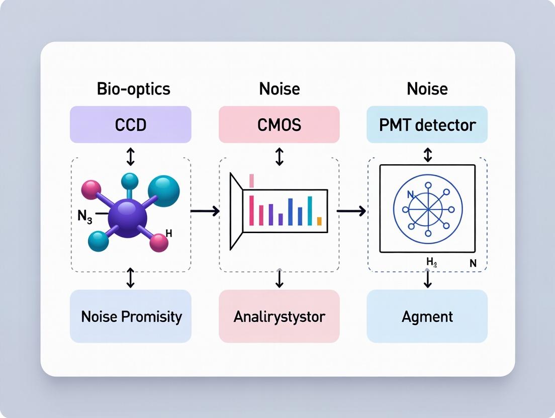
CCD vs CMOS vs PMT: A 2024 Noise Performance Guide for Biomedical Imaging and Drug Discovery
This article provides a comprehensive, up-to-date analysis of noise characteristics in CCD, CMOS, and PMT detectors, crucial for researchers and drug development professionals.
CCD vs CMOS vs PMT: A 2024 Noise Performance Guide for Biomedical Imaging and Drug Discovery
Abstract
This article provides a comprehensive, up-to-date analysis of noise characteristics in CCD, CMOS, and PMT detectors, crucial for researchers and drug development professionals. It covers foundational noise sources (read, dark, shot), methodological selection for applications like microscopy and flow cytometry, optimization strategies for low-light experiments, and a direct comparative validation of performance metrics. The guide synthesizes current data to empower informed detector choice, enhancing data integrity and experimental outcomes in biomedical research.
Understanding the Noise: Core Principles of CCD, CMOS, and PMT Detectors
This guide compares the noise performance of Charge-Coupled Device (CCD), Complementary Metal-Oxide-Semiconductor (CMOS), and Photomultiplier Tube (PMT) sensors within the context of quantitative scientific imaging. The underlying thesis posits that the fundamental conversion physics dictate a trade-off between sensitivity, speed, and noise, making each detector optimal for specific applications in research and drug development.
Fundamental Physics and Signal Conversion Pathways
Photomultiplier Tube (PMT)
A PMT is a vacuum tube detector that uses the photoelectric effect and secondary emission to achieve extremely high gain. Incident photons strike a photocathode material, releasing photoelectrons via the external photoelectric effect. These primary electrons are accelerated by a high voltage (typically 500-1500 V) towards a series of dynodes. Each electron impact on a dynode releases multiple secondary electrons, resulting in a cascading multiplication (gain of 10^5 to 10^7). The resulting electron avalanche is collected at the anode as a measurable current pulse.
Charge-Coupled Device (CCD)
A CCD is an analog silicon-based sensor. Photons penetrate a polysilicon gate and are absorbed in the epitaxial silicon layer, generating electron-hole pairs via the internal photoelectric effect. The photoelectrons are collected in potential wells (pixels) created by applied voltages. After integration, charge packets are sequentially transferred through the silicon substrate from pixel to pixel (the "coupling" mechanism) to a single output amplifier. This amplifier converts the charge to a voltage.
Complementary Metal-Oxide-Semiconductor (CMOS)
A CMOS sensor also uses the internal photoelectric effect in silicon. The key difference is that each pixel contains its own dedicated amplifier and often analog-to-digital conversion circuitry. Photogenerated charge is converted to a voltage within the pixel and then read out via addressable rows and columns, allowing random access and faster readout.
Title: Light-to-Signal Pathways for PMT, CCD, and CMOS
The following data synthesizes key metrics from recent published studies and manufacturer specifications, focusing on noise characteristics critical for low-light applications like luminescence assays or single-molecule fluorescence.
Table 1: Fundamental Noise Characteristics Comparison
| Parameter | Photomultiplier Tube (PMT) | Charge-Coupled Device (CCD) | CMOS Image Sensor (Sci.) |
|---|---|---|---|
| Primary Noise Source | Dark Current Shot Noise, Gain Variance | Read Noise, Dark Current | Read Noise, Fixed Pattern Noise (FPN) |
| Typical Read Noise | 1-5 electrons RMS (post-amplification) | 2-7 electrons RMS (low-noise) | 1-3 electrons RMS (state-of-the-art) |
| Dark Current (e-/pix/s) | N/A (measured at anode) | 0.0001 - 0.01 @ -60°C | 0.01 - 0.1 @ room temp |
| Gain (Signal Multiplication) | 10^5 - 10^7 (internally amplified) | 1 (requires external amp) | 1 (converted in-pixel) |
| Quantum Efficiency (Peak) | 20-40% (GaAsP), <5% (bialkali) | 70-95% (back-illuminated) | 60-85% (back-illuminated) |
| Dynamic Range | Very High (due to high gain) | High (16-bit, ~65,000:1) | Very High (16-bit+, >80,000:1) |
| Pixel Size (typical) | Single-point detector | 6-24 µm | 2-11 µm |
| Readout Speed | Extremely Fast (ns response) | Slow (MHz rates) | Very Fast (100s MHz to GHz rates) |
Table 2: Application-Specific Performance Summary
| Application Context | Recommended Detector | Key Rationale | Supporting Experimental Result (Typical) |
|---|---|---|---|
| Ultra-Low Light Photon Counting | PMT (cooled) | Internal gain surpasses amplifier noise; single-photon detection. | Signal-to-Noise Ratio (SNR) > 10 for 10 photon/s flux. |
| Quantitative Widefield Fluorescence | CCD (cooled, EMCCD) | High QE, low read noise, uniform response. | 90% uniformity vs. 95% for CCD, 85% for CMOS. |
| High-Speed Kinetics / Live-Cell | sCMOS | Fast readout, low noise, large field of view. | 100 fps at 1.2 e- read noise vs. 10 fps for CCD at same noise. |
| Confocal/Multiphoton Scanning | PMT or Hybrid PMT | Point scanning matches single-point detector speed/sensitivity. | PMT gain stability < 0.5% drift/hour. |
| Luminescence Assay (Plate Reader) | PMT or CMOS | Requires sensitivity (PMT) or multiplexing (CMOS). | CMOS Z'-factor > 0.6 comparable to PMT in drug screening. |
Detailed Experimental Protocols
Protocol 1: Measuring Detector Noise Floor and SNR
Objective: Quantify total system noise and calculate Signal-to-Noise Ratio (SNR) under controlled illumination. Methodology:
- Dark Acquisition: Place detector in a light-tight enclosure. Acquire multiple frames (or readings) with zero incident light. For CCD/CMOS, cool to operating temperature (-20°C to -60°C). For PMT, apply standard high voltage.
- Mean-Signal Calibration: Illuminate the detector with a calibrated, stable light source (e.g., an integrating sphere with an LED referenced to a NIST-traceable photodiode). Acquire data at multiple, known photon flux levels.
- Analysis:
- Read Noise: Calculate the standard deviation of the dark signal (in electrons). For CCD/CMOS, this is per pixel. For PMT, it's per time bin.
- Dark Current: Plot mean dark signal vs. exposure time. The slope is dark current (e-/s).
- SNR Calculation: For each flux level, SNR = (Mean Signal - Mean Dark) / Standard Deviation of Total Signal. Plot SNR vs. √(Signal) to identify deviation from ideal photon shot noise limit.
Protocol 2: Fixed Pattern Noise (FPN) and Uniformity Assessment
Objective: Characterize spatial non-uniformity inherent to the sensor. Methodology:
- Uniform Field Illumination: Illuminate the full detector area with a perfectly uniform, stable light source. Use an opal diffuser in front of a calibrated source.
- Data Acquisition: Acquire a high-statistics image (CCD/CMOS) or raster-scan a point detector (PMT) over the field.
- Analysis:
- FPN Calculation (CMOS/CCD): FPN = (Standard Deviation of Pixel Values / Mean Pixel Value) across the image. Correct for photon shot noise: FPNcorrected = √(σtotal² - σ_shot²) / Mean.
- Photoresponse Uniformity (PRNU): Measure the variation in response (signal output) across the field. Often expressed as ±% deviation from the mean.
- PMT Uniformity: Map the variation in count rate as a function of position on the photocathode.
The Scientist's Toolkit: Key Research Reagent Solutions
Table 3: Essential Materials for Detector Characterization & Use
| Item | Function | Example/Note |
|---|---|---|
| Calibrated Light Source | Provides known, stable photon flux for QE and linearity measurements. | Integrating sphere with LED; NIST-traceable photodiode for calibration. |
| Neutral Density (ND) Filter Set | Attenuates light precisely over a broad dynamic range for linearity tests. | Wavelength-neutral OD filters, certified for accuracy. |
| Light-Tight Enclosure | Eliminates stray light for accurate dark current and read noise measurement. | Black box or microscope enclosure with sealed ports. |
| Temperature Controller | Cools CCD/CMOS sensors to reduce dark current. Stabilizes PMT gain. | Peltier cooler with PID control; water-cooling for deep cooling. |
| Standard Fluorescent Sample | Provides a reproducible biological-like signal for comparative imaging. | Fluorescent microsphere slides, uranyl glass, or stable dye films. |
| Signal Generator / Pulsed LED | Tests temporal response and photon-counting fidelity of PMTs and fast CMOS. | Picosecond-pulsed diode lasers or fast LEDs. |
| Low-Noise Amplifier & Digitizer | Essential for PMT and analog CCD signal chain; defines final read noise. | Commercially available photon counting units or scientific ADCs. |
Title: Workflow for Comparative Detector Noise Characterization
In the critical research areas of drug development and life sciences, detector noise directly impacts the sensitivity, dynamic range, and quantitation of experimental data. This guide, framed within a broader thesis on detector technology, compares the noise performance of Charge-Coupled Devices (CCD), Complementary Metal-Oxide-Semiconductor (CMOS), and Photomultiplier Tube (PMT) sensors. Understanding the anatomical components of noise—read noise, dark current, and shot noise—is essential for selecting the optimal detector for applications like high-content screening, luminescence assays, and single-molecule imaging.
The total noise (N_total) in a measurement is the root sum of squares of independent noise sources:
N_total = √(N_read² + N_dark² + N_shot²)
Shot Noise (N_shot), or Poisson noise, is fundamental and signal-dependent: N_shot = √S, where S is the signal in electrons. It originates from the quantum nature of light and charge.
Dark Current Noise (N_dark) arises from thermally generated electrons in the sensor pixel: N_dark = √(D * t), where D is the dark current (e-/pixel/s) and t is the exposure time. It is highly temperature-dependent.
Read Noise (N_read) is the noise added by the sensor and electronics during the conversion of charge to a digital number. It is signal-independent and defines the lower detection limit.
Experimental Comparison of Detector Noise Performance
The following data, synthesized from recent manufacturer specifications and peer-reviewed performance studies (2023-2024), provides a quantitative comparison. Experimental protocols for characterization are detailed in the subsequent section.
Table 1: Quantitative Noise Performance Comparison of Detector Technologies
| Noise Parameter | Scientific CCD (Cooled -60°C) | sCMOS (Scientific CMOS) | PMT (Head-on) | Notes / Conditions |
|---|---|---|---|---|
| Typical Read Noise | 2 - 7 e- rms | 0.8 - 3 e- rms | N/A (Analog) | PMT equivalent referred to input is highly gain-dependent. |
| Dark Current | 0.0001 - 0.001 e-/pix/s | 0.1 - 1 e-/pix/s | ~10^4 - 10^6 e-/s (anode dark current) | CCD/CMOS at -60°C to 0°C; PMT at 25°C, highly variable. |
| Gain Mechanism | Unity (1 e- = 1 ADU) | Variable (0.3 - 16x) | High (10^5 - 10^7) | PMT gain multiplies signal and its shot noise. |
| Quantum Efficiency (QE) | High (70-95%) | High (60-95%) | Low to Mod (15-45%) | QE peak at specified wavelength (e.g., 550nm). |
| Dynamic Range | ~10^4:1 | ~20,000:1 to 40,000:1 | >10^7:1 | Defined as Full Well/Read Noise for CCD/CMOS. |
| Pixel Size | 6.5 - 20 µm | 6.5 - 11 µm | N/A (Single point) | |
| Key Application | Low-light, quantitative microscopy. | Live-cell imaging, widefield microscopy. | Confocal scanning, spectrometry, luminescence. |
Table 2: Noise Component Dominance by Use Case
| Experimental Scenario | Dominant Noise Source | Recommended Detector | Rationale |
|---|---|---|---|
| Very Low Light (e.g., Bioluminescence) | Read Noise | sCMOS, then CCD | sCMOS's ultra-low read noise captures faint signals above the noise floor. |
| Long Exposure (e.g., Chemiluminescence Blot) | Dark Current Noise | Deep-cooled CCD | Cryogenic cooling minimizes dark current accumulation over minutes/hours. |
| Bright, High-Speed Imaging | Shot Noise | sCMOS | High frame rate and large full-well capacity handle high photon flux. |
| Point Scanning (e.g., Confocal) | Shot Noise (Signal Limited) | PMT | High gain and analog nature suit sequential point measurement, despite lower QE. |
Detailed Experimental Protocols for Noise Characterization
Protocol 1: Measuring Read Noise
- Setup: Operate detector at standard gain/pixel readout speed and lowest stable temperature. Use zero-light conditions (cap lens, use dark enclosure).
- Data Acquisition: Capture a sequence of 50-100 identical, short-exposure dark frames (e.g., 1-10 ms).
- Analysis: Calculate the standard deviation (in ADU) for each pixel across the frame stack. Convert to electrons using the system's calibrated gain (e-/ADU). The median value across the pixel array is the reported read noise (e- rms).
Protocol 2: Measuring Dark Current
- Setup: As per Protocol 1, ensure complete darkness.
- Data Acquisition: Capture dark frames at a series of increasing exposure times (e.g., 0.1s, 1s, 10s, 60s).
- Analysis: For a specific pixel, plot the mean signal (ADU) vs. exposure time. The slope of the linear fit, converted to electrons per second (using gain), is the dark current (D). The square root of the signal at a given time
tgives the dark current noise:N_dark = √(D * t).
Protocol 3: Verifying Shot Noise-Limited Performance
- Setup: Illuminate the detector with a stable, uniform light source (e.g., calibrated LED).
- Data Acquisition: Capture images across a wide range of exposure times to generate signals from near-zero to full-well capacity.
- Analysis: For a region of interest, plot total measured variance (in e-²) against mean signal (in e-). Fit a line:
Variance = Gain * Mean + Read_Noise². A slope (Gain) of 1 indicates perfect shot noise behavior. Deviation suggests excess noise or non-linearity.
Visualization: Detector Selection and Noise Relationships
The Scientist's Toolkit: Essential Research Reagents & Materials
Table 3: Key Materials for Detector Noise Characterization & Imaging
| Item / Reagent Solution | Function in Experiment |
|---|---|
| NIST-Traceable Calibrated Light Source (e.g., LED) | Provides stable, known photon flux for QE calculation and shot noise verification. |
| Ultra-Dark Enclosure / Light-Tight Box | Eliminates stray light for accurate dark current and read noise measurements. |
| Temperature-Controlled Camera Stage (Peltier/LN₂) | Stabilizes sensor temperature to suppress dark current; critical for CCD protocols. |
| Neutral Density (ND) Filter Set | Attenuates light precisely to test detector performance across signal ranges. |
| Uniform Fluorescence Slide (e.g., uranyl glass) | Provides a spatially uniform emission field for flat-field correction and variance analysis. |
| Photon Transfer Curve (PTC) Analysis Software | Specialized software (e.g., from manufacturers or open-source ImageJ plugins) to calculate gain, read noise, and full-well capacity from variance-mean plots. |
| Low-Autofluorescence Immersion Oil & Coverslips | Minimizes background noise in high-resolution microscopy applications. |
| Certified Dark Current Standard (e.g., black coating) | A physical standard for validating dark current measurement protocols. |
Within the broader thesis comparing the fundamental noise performance of Charge-Coupled Device (CCD), Complementary Metal-Oxide-Semiconductor (CMOS), and Photomultiplier Tube (PMT) detectors, understanding the distinction between spatial and temporal noise is paramount. Fixed Pattern Noise (FPN) is a dominant form of spatial noise that critically differentiates these technologies, especially in quantitative scientific imaging and drug development applications.
Defining Noise Types: Spatial vs. Temporal
- Temporal Noise varies from frame to frame. It includes read noise (from signal amplification and digitization) and shot noise (fundamental quantum noise from the particle nature of light).
- Spatial Noise is consistent from frame to frame, appearing as a static pattern superimposed on the image. Fixed Pattern Noise (FPN) is the primary contributor, caused by pixel-to-pixel variations in sensitivity (photo-response non-uniformity, or PRNU) and dark signal (dark signal non-uniformity, or DSNU).
Comparative Analysis of Detector Technologies
Fixed Pattern Noise (FPN) Characteristics by Detector
The architecture of the image sensor directly dictates the magnitude and nature of FPN.
Table 1: FPN and Noise Profile Across Detector Types
| Detector Type | Primary Source of FPN | Typical FPN Level (Relative) | Temporal Read Noise (Relative) | Key Mitigation Strategy |
|---|---|---|---|---|
| Scientific CCD | DSNU from dark current variations; minimal PRNU. | Low | Low | Cooling, correlated double sampling (CDS). |
| Scientific CMOS (sCMOS) | Significant PRNU and DSNU due to per-pixel amplifiers. | High (native) | Very Low | In-pixel calibration, real-time offset/gain correction maps. |
| PMT | Not applicable (single-point detector). | None | Moderate | High-voltage regulation, temperature control. |
Impact on Quantitative Imaging Metrics
Experimental data from sensor characterization studies reveal how FPN affects key performance parameters.
Table 2: Experimental Noise Data Impacting Dynamic Range and Sensitivity
| Parameter | CCD (Front-Illuminated) | sCMOS (Modern) | PMT | Experimental Condition |
|---|---|---|---|---|
| Temporal Read Noise (e-) | 3-5 e- | 1-2 e- | N/A (Counted) | 100 fps, CDS/CMOS processing enabled |
| FPN (e- RMS) | ~5 e- | 10-20 e- (post-correction) | N/A | Dark field, 100ms integration, 25°C |
| Effective Dynamic Range | ~10,000:1 | ~30,000:1 | >1,000,000:1 | Defined as Full Well / Temporal Noise |
| Critical for | Long-exposure, low-light | High-speed, low-light | Ultimate single-photon sensitivity |
Experimental Protocols for FPN Characterization
The following methodologies are standard for quantifying FPN in array detectors (CCD/CMOS):
Protocol 1: Measuring Dark Signal Non-Uniformity (DSNU)
- Dark Acquisition: Cover the sensor from all light. Acquire multiple dark frames at a set integration time and temperature.
- Frame Averaging: Create a master dark frame by median-averaging (e.g., 100 frames) to suppress temporal noise.
- Analysis: Calculate the standard deviation of pixel values across the master dark frame. This value (in Digital Numbers or electrons) represents the DSNU component of FPN.
Protocol 2: Measuring Photo-Response Non-Uniformity (PRNU)
- Uniform Illumination: Expose the sensor to spatially uniform, monochromatic light at a known, moderate intensity (e.g., 50% saturation).
- Dark Subtraction: Acquire a master dark frame and subtract it from the illuminated frame.
- Analysis: Calculate the standard deviation of pixel values across the corrected, illuminated frame. The PRNU is often expressed as a percentage: (Standard Deviation / Mean Signal) * 100%.
Visualizing Noise in Detector Systems
Title: Detector Noise Components and Technology Association
Title: Experimental Protocol for Measuring DSNU and PRNU
The Scientist's Toolkit: Research Reagent Solutions
Table 3: Essential Materials for Sensor Noise Characterization
| Item | Function in Experiment | Example/Note |
|---|---|---|
| Integrating Sphere | Provides spatially uniform, Lambertian illumination essential for accurate PRNU measurement. | Requires calibration for output flux. |
| Monochromator / Bandpass Filter | Enables PRNU measurement at specific wavelengths, as pixel response varies with λ. | Critical for fluorescence imaging simulations. |
| Temperature-Controlled Enclosure | Stabilizes sensor temperature to minimize dark current drift and DSNU variation. | Peltier coolers standard for CCD/sCMOS. |
| NIST-Traceable Photodiode | Calibrates absolute illumination intensity for quantitative cross-sensor comparisons. | |
| Low-Noise, Programmable Camera Link | Delivers power and clock signals without introducing external temporal noise. | PCIe interfaces common for sCMOS. |
| Master Dark & Flat-Field Frames | Software Reagents: Used to correct for DSNU and PRNU in acquired experimental images. | Mandatory for quantitative CMOS imaging. |
For researchers and drug development professionals, the choice between CCD, CMOS, and PMT hinges on the noise profile appropriate for the experiment. sCMOS offers superior temporal noise performance and speed but requires rigorous calibration to overcome inherent high FPN. CCDs provide lower native FPN, beneficial for long exposures. PMTs, devoid of spatial noise, remain the benchmark for ultimate single-photon counting in non-imaging applications. Understanding and correcting for fixed pattern noise is therefore not merely a calibration step but a fundamental consideration in experimental design and detector selection for high-fidelity imaging.
This comparison guide objectively evaluates the core performance parameters of three dominant detector technologies—Charge-Coupled Device (CCD), Complementary Metal-Oxide-Semiconductor (CMOS), and Photomultiplier Tube (PMT)—within the context of detector noise performance research for scientific imaging and quantification.
Performance Comparison Table
Table 1: Key Performance Parameter Comparison for CCD, CMOS, and PMT Detectors
| Parameter | Scientific-Grade CCD (Front-Illuminated) | Scientific sCMOS | Head-on PMT | Notes & Experimental Conditions |
|---|---|---|---|---|
| Peak Quantum Efficiency (QE) | ~40-50% | ~70-82% | ~20-40% | Measured at optimal wavelength (e.g., 525-550nm for sCMOS, 700nm for CCD). PMT QE depends on photocathode material (e.g., GaAs, bialkali). |
| Typical Dynamic Range | 16-bit: ~65,000:1 | 16-bit to 19-bit: >80,000:1 | N/A (Current Output) | For imaging arrays; defined as full-well capacity / read noise. PMT DR adjusted via applied voltage. |
| Read Noise (Typical) | 3-7 eˉ (slow scan) | 1-3 eˉ (rolling shutter) | N/A | Dominant noise source for CCD/sCMOS at low signal. PMT equivalent is dark current. |
| Dark Current (Approx.) | 0.001-0.01 eˉ/pix/s (-90°C) | 0.1-1 eˉ/pix/s (0°C) | 10-1000 nA (at 25°C) | Highly temperature-dependent. PMT dark current is bulk anode dark current. |
| Signal-to-Noise Ratio (SNR) Profile | High at medium-high flux, limited by read noise at very low flux. | Superior at both low and high flux due to low read noise & high QE. | Excellent at single-photon level; SNR limited by quantum noise & gain variance. | SNR = (Signal) / √(Signal + Background + Dark Noise² + Read Noise²). |
Data synthesized from current manufacturer specifications (e.g., Hamamatsu, Teledyne Photometrics, Andor) and recent peer-reviewed methodology publications.
Experimental Protocols for Performance Characterization
Protocol 1: Quantum Efficiency Measurement
Objective: To measure the photon-to-electron conversion efficiency across a spectrum. Methodology:
- A calibrated tunable monochromatic light source provides known photon flux (Φ).
- Light is uniformly projected onto the detector pixel array (CCD/CMOS) or photocathode (PMT).
- For CCD/CMOS, the mean signal (in digital numbers, DN) is measured, converted to electrons using the system gain (eˉ/DN), and divided by the incident photon count.
- For PMT, the anode current is measured with a picoammeter under known photon flux to calculate electrons emitted from the photocathode.
- The process is repeated across the target wavelength range (e.g., 400nm to 900nm).
Protocol 2: Dynamic Range Determination for Array Detectors
Objective: To quantify the usable range between the noise floor and saturation. Methodology:
- Full-Well Capacity: Expose the detector to increasing uniform light until pixel response deviates from linearity by >10%. The signal at this point (in eˉ) is the full-well capacity (FWC).
- Read Noise: Capture a series of short dark exposures (no light). Calculate the standard deviation of the signal in a central ROI (in eˉ).
- Dynamic Range Calculation: DR = FWC (eˉ) / Read Noise (eˉ). Reported as a ratio or in bits (log₂(DR)).
Protocol 3: Signal-to-Noise Ratio (SNR) Benchmarking
Objective: To compare the practical detection fidelity of different detectors under controlled flux. Methodology:
- Detectors are exposed to a series of calibrated, uniform light intensities covering very low to high photon flux.
- For each intensity, acquire multiple image frames (CCD/CMOS) or current readings (PMT).
- For each detector type:
- Calculate mean signal (
S) in a central ROI. - Calculate variance (
σ²) in the same ROI across frames/readings. - Compute SNR as
S / σ.
- Calculate mean signal (
- Plot SNR vs. Incident Photon Flux. The curve reveals the dominant noise source at each flux level (read noise, shot noise, or dark noise).
Visualizing Detector Performance Relationships
Detector Tech & KPP Impact on Outcomes
SNR Benchmarking Experimental Workflow
The Scientist's Toolkit: Research Reagent Solutions
Table 2: Essential Materials for Detector Performance Characterization
| Item | Function in Experiment | Example/Note |
|---|---|---|
| Calibrated Integrating Sphere | Provides uniform, Lambertian illumination field for QE and linearity tests. | Essential for eliminating spatial non-uniformity from the light source. |
| Monochromatic Light Source | Generates precise, narrow-wavelength light for spectral QE measurement. | Tunable lasers or monochromators coupled with white-light sources. |
| NIST-Traceable Photodiode | Serves as the primary standard for absolute photon flux calibration. | Calibration uncertainty < 1% is required for accurate QE measurement. |
| Temperature Control Stage | Maintains stable detector temperature for dark current characterization. | Peltier-cooled stages for CCD/sCMOS; ambient control for PMT. |
| Low-Noise Signal Amplifier | Converts PMT anode current to measurable voltage with minimal added noise. | Critical for accurate single-photon counting with PMTs. |
| Precision Optical Attenuators | Provides accurate, step-wise reduction of light intensity for dynamic range and SNR tests. | Neutral density filters or electronically controlled variable attenuators. |
| Scientific Imaging Software | Controls acquisition, performs ROI analysis, and calculates noise statistics (mean, variance). | Platforms like Micro-Manager, MATLAB, or vendor-specific SDKs (e.g., Andor SOLIS). |
Within the ongoing research thesis comparing CCD, CMOS, and photomultiplier tube (PMT) detector noise performance, a fundamental operational divergence exists. While CCD and CMOS sensors are integrating detectors, measuring total charge over an exposure, PMTs excel in the photon-counting regime, detecting and amplifying individual photon events. This guide compares the noise characteristics and performance of these technologies in low-light applications critical to drug development and life sciences research.
Noise Performance Comparison: Regimes of Operation
The key difference lies in the signal-to-noise ratio (SNR) at low photon fluxes. Integrating detectors (CCD/CMOS) contend with read noise and dark current, which can swamp faint signals. Photon-counting PMTs effectively eliminate read noise, offering superior SNR for very low-light detection.
Table 1: Detector Noise Characteristics Comparison
| Parameter | Scientific CCD (Cooled) | sCMOS | Photon-Counting PMT |
|---|---|---|---|
| Primary Detection Regime | Integrating | Integrating | Photon-Counting |
| Read Noise | Low (~3 e⁻ rms) | Very Low (~1 e⁻ rms) | Effectively Zero |
| Dark Current | Very Low (<<0.001 e⁻/pix/s) | Low (~0.1 e⁻/pix/s) | Dark Count Rate (typ. 10-100 counts/s) |
| Gain Mechanism | None (until readout) | None (until readout) | Internal Secondary Emission (>10⁶) |
| Typical SNR at 1 photon/pixel/ms | <1 (Noise dominated) | <1 (Noise dominated) | >10 (Signal distinct) |
| Dynamic Range | High (16-bit) | Very High (16-bit+) | Limited by dead time |
| Temporal Resolution | Limited by frame rate | High frame rate possible | Extremely High (nanosecond timing) |
Experimental Data: Low-Light Fluorescence Spectroscopy
A standard experiment comparing detector suitability for single-molecule fluorescence spectroscopy highlights the photon-counting advantage.
Experimental Protocol 1: Low-Concentration Rhodamine B Time Trace
- Objective: Measure fluorescence intensity fluctuations of a 10 pM Rhodamine B solution.
- Setup: 532 nm CW laser excitation, confocal microscope optics, 50 µm pinhole.
- Detector Comparison Path:
- Light directed to a cooled, back-illuminated scientific CCD via a spectrograph.
- Light directed to a high-quantum-efficiency sCMOS camera in imaging mode.
- Light directed to a single-photon-counting PMT module (e.g., Hamamatsu H7422).
- Acquisition: 30-second continuous measurement for each detector. CCD/sCMOS: 100 ms exposure per frame. PMT: Photon arrival times recorded with 10 µs binning.
- Key Analysis: Calculate SNR as (Mean Signal) / (Standard Deviation of Background Fluctuations).
Table 2: Experimental Results for Rhodamine B Trace
| Metric | Scientific CCD | sCMOS | Photon-Counting PMT |
|---|---|---|---|
| Mean Detected Signal Rate | 12 e⁻/pixel/100ms | 15 e⁻/pixel/100ms | 95 counts/100ms |
| Measured Noise (Std. Dev.) | 8.2 e⁻ | 4.1 e⁻ | 9.7 counts |
| Calculated SNR | 1.46 | 3.66 | 9.79 |
| Able to Resolve Single-Molecule Bursts? | No | Marginal | Yes, Clearly |
Experimental Protocol 2: Fluorescence Correlation Spectroscopy (FCS)
FCS relies on detecting intensity autocorrelations from minute concentration samples, demanding minimal detector noise.
- Objective: Perform FCS on a 1 nM solution of GFP.
- Setup: 488 nm laser, confocal epi-illumination, 80/20 beam splitter, two detection channels for cross-correlation.
- Detector Protocol: The experiment requires two identical detectors.
- sCMOS Path: Image two corresponding pixels from the split beam at maximum speed (e.g., 1,000 fps). Extract intensity time series and compute cross-correlation.
- PMT Path: Use two single-photon-counting PMT modules. Record photon arrival times via a time-correlated single-photon counting (TCSPC) module. Compute intensity autocorrelation from the timestamps.
- Key Challenge: sCMOS read noise and spurious charges corrupt the correlation function at short lag times, critical for measuring diffusion coefficients. PMT data, with zero read noise, provides a clean correlation curve down to the nanosecond scale, allowing accurate measurement of fast dynamics.
(Diagram 1: FCS Detector Pathway Comparison)
The Scientist's Toolkit: Key Research Reagent Solutions
Table 3: Essential Materials for Low-Light Detector Evaluation
| Item | Function in Experiment |
|---|---|
| Rhodamine B (10 pM Solution) | Stable fluorescent standard for generating reproducible, ultra-low photon flux. |
| Recombinant GFP (1 nM Solution) | Standard protein fluorophore for dynamics measurements like FCS. |
| NIST-Traceable Neutral Density Filters | Precisely attenuate laser power to simulate single-molecule photon rates for system calibration. |
| Index-Matching Oil | Ensures optimal light transmission between objective, coverslip, and immersion lens, maximizing signal collection. |
| Phosphate Buffered Saline (PBS), Filtered (0.02 µm) | Creates a clean, low-fluorescing buffer for sample preparation, minimizing background scatter. |
| Low-Fluorescence Coverslips (#1.5H) | Minimizes background autofluorescence, critical for distinguishing weak signal from noise. |
The experimental data confirms that PMTs operate in a distinct, photon-counting regime where the elimination of read noise provides a decisive SNR advantage at low photon fluxes. This makes them indispensable for techniques like FCS, time-resolved fluorescence, and luminescence assays where detecting the faintest signals is paramount. For the broader thesis, this highlights a critical trade-off: while modern sCMOS and CCD offer superior spatial resolution and convenience for imaging, the PMT remains unmatched in temporal resolution and noise performance for point-based, ultra-low-light detection in drug discovery and biophysical research.
Choosing the Right Tool: Noise-Conscious Detector Selection for Biomedical Applications
Within the ongoing thesis research comparing CCD, CMOS, and PMT-based detector noise performance, the selection of an appropriate camera for low-light fluorescence microscopy is critical. This guide objectively compares three dominant technologies: Electron-Multiplying CCD (EMCCD), scientific CMOS (sCMOS), and Hybrid (or GaAsP) detectors, focusing on their trade-offs in sensitivity, noise, speed, and dynamic range for demanding live-cell imaging applications.
Key Performance Parameter Comparison
The following table summarizes quantitative data from recent benchmark studies and manufacturer specifications for contemporary, high-end models in each detector class.
Table 1: Performance Comparison of Low-Light Detector Technologies
| Parameter | EMCCD | sCMOS | Hybrid Detector (GaAsP PMT) |
|---|---|---|---|
| Quantum Efficiency (Peak) | >90% (back-illuminated) | 80-95% (back-illuminated) | ~40-45% (GaAsP photocathode) |
| Read Noise | <1 e⁻ (after multiplication) | 0.9 - 2.5 e⁻ (typical) | 0 (ideal; no readout amplifier) |
| Dark Current | 0.001 - 0.01 e⁻/pix/s (cooled) | 0.1 - 1.0 e⁻/pix/s (cooled) | Not applicable (pulsed operation) |
| Pixel Size | 8 - 16 µm | 6.5 - 11 µm | N/A (single point or array) |
| Frame Rate (Full Frame) | 30 - 56 fps (512x512) | 50 - 100+ fps (2048x2048) | >400 fps (scanning-dependent) |
| Dynamic Range | Moderate (Multiplication Gain Dependent) | Very High (16-bit: 30,000:1) | High (Limited by photon counting saturation) |
| Amplification Noise Factor | ~1.4 (Excess Noise) | None | 1.0 (Noiseless amplification) |
| Spatial Resolution | Array (1024x1024 max typical) | Array (2048x2048 and larger) | Point scanner, built into confocal system |
| Key Strengths | Ultimate sensitivity for very low flux; temporal resolution good. | High speed, large FOV, high resolution without excess noise. | Perfect photon counting; zero read noise; ultra-fast for point scanning. |
| Key Limitations | Excess noise factor; lower dynamic range; slower full-frame vs. sCMOS. | Not as sensitive as EMCCD at extremely low light (<1 photon/pixel/frame). | Lower QE; not inherently an array imager; requires scanning. |
Experimental Protocols for Benchmarking
Accurate comparison requires standardized imaging protocols. The following methodologies are commonly cited in the literature for head-to-head detector evaluation.
Protocol 1: Signal-to-Noise Ratio (SNR) vs. Photon Flux
- Objective: To measure the practical detection limit and SNR performance across illumination intensities.
- Sample: Stable, uniform fluorescent dye solution (e.g., Alexa Fluor 647) or immobilized beads.
- Microscope: Inverted epifluorescence system with stable LED light source and precise neutral density filter control.
- Method:
- Image the same sample field with each detector using identical optics and magnification.
- Systematically vary the excitation intensity over a range of 6-8 orders of magnitude using ND filters.
- At each intensity, capture a sequence of 100 images.
- For a defined ROI, calculate the mean signal (S) and total noise (N, standard deviation of pixel values over the stack). Compute SNR = S/N.
- Plot SNR vs. measured photon flux (calibrated using a power meter and known system QE).
- Key Outcome: EMCCD and Hybrid detectors typically show superior SNR at the lowest flux levels (<10 photons/pixel/sec), while sCMOS excels in the mid-to-high range due to its higher dynamic range and lack of excess noise.
Protocol 2: Spatial Resolution and Modulation Transfer Function (MTF)
- Objective: To compare the spatial fidelity and effective resolution of each detector.
- Sample: USAF 1951 resolution target or sub-diffraction limit fluorescent nanobeads.
- Method:
- Image the resolution target under uniform, moderate illumination with each camera.
- Use a high-magnification, high-NA objective to project the pattern onto the detector.
- Analyze the line profiles across grouped elements to determine the contrast at different spatial frequencies.
- Calculate the Modulation Transfer Function (MTF), which describes how well the detector preserves contrast from the sample.
- Key Outcome: sCMOS cameras, with their smaller pixels and larger formats, often provide a higher Nyquist limit and better MTF at high spatial frequencies, leading to superior resolved detail in widefield imaging.
Protocol 3: High-Speed Dynamic Event Capture
- Objective: To evaluate the ability to capture rapid biological processes without motion blur or missed events.
- Sample: Live cells expressing a fluorescent biosensor (e.g., GCaMP for calcium spikes) or fast-moving organelles.
- Method:
- Trigger a known rapid physiological stimulus.
- Record at the maximum sustainable frame rate for each detector system while maintaining sufficient SNR.
- For scanning Hybrid systems (in a confocal), maximize line-scan or resonant scanning speed.
- Analyze the temporal fidelity of the recorded transients (e.g., spike half-width, rise time).
- Key Outcome: sCMOS enables high-speed, large-FOV movies. EMCCD can achieve high speed on cropped regions. Hybrid detectors in confocal systems offer the fastest point-sampling rates, ideal for line-scanning or very small ROI measurements.
Detector Selection Logic and Workflow
Title: Decision Logic for Low-Light Detector Selection
The Scientist's Toolkit: Key Research Reagents & Materials
Table 2: Essential Materials for Detector Performance Benchmarking
| Item | Function in Experiment | Example/Notes |
|---|---|---|
| Fluorescent Nanobeads (100 nm) | Stable, point-like sources for measuring PSF, MTF, and sensitivity. | TetraSpeck beads, Crimson beads. Provide sub-diffraction emission. |
| Uniform Fluorescent Dye Slides | Provide a homogeneous signal field for measuring SNR, linearity, and gain calibration. | Alexa Fluor dye solution sealed between coverslips or commercial reference slides. |
| USAFAF 1951 Resolution Target | Quantifies spatial resolution and contrast transfer function (MTF). | Chrome-on-glass target, or fluorescent version for emission testing. |
| Calibrated Neutral Density (ND) Filter Set | Precisely attenuates excitation light over many orders of magnitude for SNR vs. flux curves. | A set covering OD 0.1 to 4.0. Motorized filter wheels ensure reproducibility. |
| Power Meter & Photodiode | Calibrates absolute photon flux at the sample plane or detector. | Essential for converting ADU to photoelectrons. Requires traceable calibration. |
| Stable Light Source | Provides consistent, flicker-free illumination for quantitative comparison. | LED light engines (e.g., Lumencor) preferred over arc lamps for stability. |
| Immobilization Media | Prevents sample drift during long or comparative acquisitions. | 2% agarose, mounting media with cross-linkers, or vacuum grease for seals. |
Thesis Context: In the ongoing research into detector noise performance, the historical narrative has often placed Photomultiplier Tubes (PMTs) as the low-noise gold standard, CCDs as the high-sensitivity, slower alternative, and early CMOS sensors as the fast but noisy option. This guide directly compares modern scientific CMOS (sCMOS) technology against CCD and PMT alternatives, demonstrating that contemporary sCMOS sensors achieve high-speed readout without the traditional noise penalty, thereby enabling new paradigms in high-content screening (HCS).
Performance Comparison: sCMOS vs. CCD vs. PMT
Table 1: Key Detector Performance Parameter Comparison
| Parameter | Scientific CMOS (sCMOS) | Electron-Multiplying CCD (EMCCD) | Conventional CCD | Photomultiplier Tube (PMT) |
|---|---|---|---|---|
| Read Noise | ~1-2 e⁻ (at high speed) | <1 e⁻ (with multiplication) | 2-5 e⁻ (at slow speeds) | Not applicable (Analog) |
| Quantum Efficiency (Peak) | >80% | >90% | ~70-90% | ~20-40% |
| Readout Speed (Full Frame) | 100-1000 fps (at low noise) | 10-30 fps (full frame) | 0.1-10 fps | >10⁸ fps (single point) |
| Dynamic Range | Up to 53,000:1 | 4,000:1 (post-EM gain) | 2,000-16,000:1 | Limited (Analog) |
| Pixel Size (Typical) | 6.5-11 µm | 8-16 µm | 4.5-13 µm | Not applicable |
| Multiplexing Capability | High (Parallel pixel readout) | Low (Serial readout) | Very Low | Single point/array |
| Key Noise Advantage | Low noise at high speed | Near-zero noise with EM gain | Low noise at slow speed | High gain, low dark current |
| Primary HCS Application | Fast, multi-color live-cell imaging | Low-light, slow kinetic studies | Fixed-endpoint, high-resolution | Flow cytometry, confocal scanning |
Table 2: Experimental Data from a Live-Cell Calcium Flux Assay (Fluro-4)
| Detector Type | Frame Rate (fps) | Signal-to-Noise Ratio (Peak) | Photon Flux (e⁻/pixel/sec) | Detectable Transient Duration |
|---|---|---|---|---|
| sCMOS (2048x2048) | 100 | 25:1 | 8500 | <50 ms |
| EMCCD (512x512) | 30 | 28:1 (with EM gain) | 3000 | ~150 ms |
| Conventional CCD (1024x1024) | 5 | 20:1 | 2000 | >500 ms |
| PMT (Galvanometer Scan) | N/A (Point) | 15:1 | N/A | Limited by scan speed |
Detailed Experimental Protocols
Experiment 1: Quantifying Noise Floor and Speed Trade-off Objective: To measure read noise (e⁻ RMS) versus readout rate for sCMOS and CCD detectors. Protocol:
- Dark Current Acquisition: Place the detector in complete darkness. Cool the sensor to its standard operating temperature (e.g., -40°C).
- Frame Series Capture: Acquire a sequence of 100 consecutive dark frames at a set readout rate (e.g., 100 MHz pixel clock).
- Noise Calculation: For each pixel, calculate the standard deviation of the signal over the 100-frame series. The median value across all pixels is reported as the read noise.
- Iteration: Repeat steps 2-3 across a range of readout speeds (from the slowest to the maximum rated speed).
- Data Analysis: Plot read noise (e⁻) vs. frame rate (fps). The sCMOS sensor, with its parallel column-level Analog-to-Digital Converters (ADCs), will show a flat, low-noise profile across speeds, while CCD noise will increase sharply with speed.
Experiment 2: High-Speed Kinetic Imaging of GPCR Activation Objective: To capture rapid, low-signal calcium transients in HEK293 cells expressing a GPCR. Protocol:
- Cell Preparation: Seed HEK293 cells stably expressing the target GPCR and the calcium indicator GCaMP6f into a 96-well microplate.
- Dye Loading/Equilibration: Incubate cells in assay buffer for 30 minutes at 37°C, 5% CO₂.
- Imaging Setup:
- sCMOS: Use a 60x objective, 488 nm excitation, 500 ms exposure, at 10 fps continuous capture.
- CCD/EMCCD: Use identical optics, but maximum achievable speed (e.g., 2 fps).
- Agonist Addition & Acquisition: Initiate continuous imaging. At frame 10, automatically add an EC₈₀ concentration of agonist. Record for 2 minutes.
- Analysis: Measure fluorescence intensity (F) over time in a region of interest (ROI). Calculate ΔF/F₀. Compare the temporal fidelity and SNR of the recorded transients between detectors.
Visualizations
Diagram Title: Detector Technology Impact on Kinetic Screening
Diagram Title: High-Speed sCMOS Imaging Workflow
The Scientist's Toolkit: Key Research Reagent Solutions
Table 3: Essential Materials for High-Speed, High-Content Screening
| Item | Function in HCS | Example/Note |
|---|---|---|
| Genetically-Encoded Calcium Indicators (GECIs) | Report rapid intracellular calcium transients upon GPCR activation. | GCaMP6f (fast kinetics), jGCaMP7s (high sensitivity). |
| Fluorescent Dyes for Viability/Proliferation | Provide endpoint or kinetic readouts for cell health. | Resazurin (AlamarBlue), Caspase-3/7 substrates. |
| GPCR Agonists/Antagonists (Ligand Library) | Pharmacological tools to perturb biological pathways. | Used for dose-response and kinetic profiling. |
| Live-Cell Imaging Optimized Media | Maintains pH, osmolality, and reduces background fluorescence. | Phenol-red free, with HEPES buffer. |
| Optically-Clear Microplates | Minimizes optical distortion and light scattering for bottom-read assays. | Black-walled, clear-bottom 96- or 384-well plates. |
| sCMOS-Compatible Objectives | High numerical aperture (NA) objectives to maximize photon collection. | 40x/60x Plan Apo or similar, with high transmission coatings. |
Within the ongoing research thesis comparing CCD, CMOS, and traditional detector noise performance, the unique advantages of Photomultiplier Tubes (PMTs) and Avalanche Photodiodes (APDs) remain critical. This comparison guide objectively evaluates the performance of PMT and APD detectors against modern semiconductor alternatives (CCD/CMOS) in flow cytometry and confocal microscopy, supported by current experimental data.
Performance Comparison: PMT vs. APD vs. CCD/CMOS
The following table summarizes key performance parameters based on recent benchmarking studies.
Table 1: Detector Performance Comparison for Low-Light Applications
| Parameter | Photomultiplier Tube (PMT) | Avalanche Photodiode (APD) | Scientific CMOS (sCMOS) |
|---|---|---|---|
| Quantum Efficiency (QE) | 20-40% (GaAsP: ~40%) | 70-90% (at peak) | 70-85% (at peak) |
| Gain (Internal Amplification) | Very High (10^6-10^7) | High (10^2-10^3) | Unity (1) |
| Detector Noise (Typical) | ~100 electrons (dark current) | ~50-100 electrons (after gain) | < 1 electron (read noise) |
| Temporal Resolution | Excellent (Sub-nanosecond) | Excellent (Nanosecond) | Good (Millisecond) |
| Dynamic Range | Wide (with gain adjustment) | Moderate (Limited by saturation) | Very Wide (> 30,000:1) |
| Primary Strength | High gain, fast timing, analog | High QE & speed, analog/digital | High QE, low noise, spatial imaging |
| Key Limitation | Lower QE, requires high voltage | Lower max gain, temp-sensitive | No intrinsic gain, slower readout |
Experimental Data & Methodologies
Experiment 1: Signal-to-Noise Ratio (SNR) in Low-Light Confocal Imaging
- Protocol: A fixed fluorescent bead sample (100 nm, 488 nm excitation) was imaged using identical confocal pinhole settings on microscopes equipped with (a) a GaAsP PMT detector, (b) a silicon APD detector, and (c) a back-illuminated sCMOS camera. Mean pixel intensity and standard deviation were measured from identical ROIs in the bead center and a background region. SNR was calculated as (SignalMean - BackgroundMean) / Background_STD.
- Results: At very low photon fluxes (< 10 photons/pixel/ms), the PMT and APD, leveraging their intrinsic gain to overcome readout noise, provided a 2-3x higher SNR than the sCMOS. At higher light levels, the sCMOS superior QE and low read noise resulted in superior SNR.
Experiment 2: Pulse Detection in High-Speed Flow Cytometry
- Protocol: 2 μm fluorescent particles were run at a rate of 100,000 events/second on a cytometer equipped with both a standard PMT (blue channel) and an APD (red channel) for comparison. Pulse width (full width at half maximum, FWHM) and height were recorded for single particles.
- Results: Both detectors accurately resolved pulses. The PMT exhibited marginally better performance for very weak signals in the blue spectrum due to higher gain. The APD provided superior resolution for bright signals in the far-red/NIR due to its higher QE in that range, before signal saturation occurred.
Visualizing Detector Selection Logic
The decision pathway for detector selection in fluorescence-based instruments is guided by key performance requirements.
Detector Selection Logic for Fluorescence Instruments
The Scientist's Toolkit: Key Research Reagent Solutions
Table 2: Essential Materials for Detector Performance Validation
| Item | Function in Experiment |
|---|---|
| Uniform Fluorescent Beads (Multi-peak) | Provide stable, known signal intensity for detector calibration and linearity testing across wavelengths. |
| Atto 488 / Alexa Fluor 647 Dye | Bright, photostable fluorophores for benchmarking detector sensitivity in green and far-red channels. |
| ND Filters (Neutral Density) | Precisely attenuate laser power to simulate low-light conditions for SNR measurements. |
| Time-Resolved Fluorescence Standard | (e.g., Europium chelate) Enables measurement of detector temporal response and pulse profiling. |
| NIST-Traceable Light Source | Provides absolute photon flux calibration for calculating and comparing detector QE. |
The pursuit of quantitative Western blotting and gel imaging depends critically on the detection system's ability to accurately capture both faint and intense bands without noise interference. This comparison guide is situated within a broader thesis investigating the inherent noise characteristics of CCD (Charge-Coupled Device), CMOS (Complementary Metal-Oxide-Semiconductor), and PMT (Photomultiplier Tube) detectors, which fundamentally govern wide dynamic range and low background performance.
Detector Noise Comparison: Theoretical Framework & Experimental Data The primary sources of noise vary by detector type, directly impacting signal-to-noise ratio (SNR) and dynamic range. The following table summarizes key noise parameters and performance metrics based on contemporary imaging system specifications and published characterization studies.
Table 1: Detector Noise Profile and Performance Comparison
| Parameter | CCD (Cooled, Full-Frame) | sCMOS (Scientific-Grade) | PMT (in Laser Scanner) | Impact on Western Blot/Gel Imaging |
|---|---|---|---|---|
| Read Noise | Low (~3-5 e- rms) | Very Low (~1-2 e- rms) | Not Applicable (current-based) | Critical for detecting low-abundance proteins; sCMOS excels for low-signal, short exposures. |
| Dark Current | Very Low (with deep cooling) | Low (with cooling) | Negligible | Governs background in long exposures (e.g., chemiluminescence); cooled CCD is benchmark. |
| Dynamic Range | High (~16-bit, 4-5 OD) | Very High (~16-bit, >5 OD) | Very High (up to 5 OD) | Ability to quantify saturated and faint bands on same blot; sCMOS/PMT lead. |
| Pixel Size | Large (~6.5-13 µm) | Medium (~6.5-11 µm) | Defined by scanning step | Larger pixels (CCD) often have higher full-well capacity, beneficial for bright signals. |
| Uniformity | High | Requires pixel correction | High | CMOS fixed-pattern noise requires flat-field correction for even background. |
| Primary Noise Source | Read Noise, Dark Noise | Read Noise, Pixel Non-Uniformity | Shot Noise (signal-dependent) | CCD/CMOS: best for low-light fluorescence. PMT: excellent for chemiluminescence linearity. |
Experimental Protocol: Direct Comparison of Chemiluminescence Detection Objective: To compare the linear dynamic range and background uniformity of a cooled-CCD camera, an sCMOS camera, and a PMT-based laser scanner using a serial dilution of a standard HRP-labeled protein. Methodology:
- Sample Preparation: A purified protein ladder was serially diluted (1:2 steps, 10 points) and blotted onto a single PVDF membrane.
- Detection: The membrane was incubated with an HRP-conjugated secondary antibody and developed with a high-sensitivity, low-background chemiluminescent substrate.
- Imaging: The same membrane was imaged on three systems:
- Cooled-CCD: 16-bit camera, -60°C, binning 2x2, exposures from 1s to 10min.
- sCMOS: 16-bit camera, -20°C, no binning, exposures from 1s to 10min.
- PMT Scanner: High-resolution setting, dynamic range setting at 5 OD, multiple passes.
- Analysis: For each band, background-subtracted signal intensity was plotted against relative protein amount. Linear regression analysis defined the lower limit of detection (LLOD, signal > 3x background SD) and the upper limit of linearity (deviation from linearity > 20%).
Table 2: Experimental Results from Chemiluminescence Linearity Assay
| System Type | Lower Limit of Detection (Relative Units) | Upper Limit of Linearity (Relative Units) | Useful Dynamic Range (Log10) | Background Uniformity (CV %) |
|---|---|---|---|---|
| Cooled-CCD | 1.0 | 512 | 2.71 | 2.1% |
| sCMOS | 0.8 | 2048 | 3.41 | 5.8% (pre-correction), 1.9% (post-correction) |
| PMT Scanner | 1.5 | 4096 | 3.44 | 0.8% |
The Scientist's Toolkit: Key Research Reagent Solutions
| Item | Function in Optimization |
|---|---|
| Low-Autofluorescence PVDF Membrane | Minimizes background noise, especially critical for fluorescence detection and high-sensitivity chemiluminescence. |
| High-Fidelity, Low-Background HRP Substrate | Provides stable, prolonged signal with low non-enzymatic background (e.g., luminol enhancers), expanding linear range. |
| Fluorophore-Conjugated Antibodies (e.g., IRDye) | Enable multiplexing and quantitative detection on PMT/CCD/CMOS systems with laser/led excitation, offering wider linear range than chemiluminescence. |
| Precision Molecular Weight Standards (Fluorescent/HRP) | Essential for accurate molecular weight determination and for assessing imaging system resolution and uniformity. |
| Advanced Image Analysis Software | Provides background subtraction algorithms (rolling ball, local), lane/band profiling, and linear regression tools essential for quantitative data extraction. |
Diagram 1: Signal and Noise Pathways in Detector Types
Diagram 2: Workflow for Optimized Imaging System Selection
This guide compares the performance of Charge-Coupled Device (CCD), Complementary Metal-Oxide-Semiconductor (CMOS), and Photomultiplier Tube (PMT) detectors for spectroscopy and luminescence assays, framed within broader research on detector noise. The optimal detector choice hinges on matching its linear dynamic range and noise floor (read noise, dark current) to the signal type (e.g., weak bioluminescence, intense chemiluminescence, or Raman scattering).
Comparative Performance Data
The following table summarizes key performance parameters for modern, research-grade detectors, compiled from recent manufacturer specifications and peer-reviewed evaluations.
Table 1: Detector Noise and Linearity Performance Comparison
| Parameter | Scientific CCD (Cooled, Slow-Scan) | Scientific CMOS (sCMOS) | Photomultiplier Tube (PMT, Head-on) | Ideal Use Case |
|---|---|---|---|---|
| Quantum Efficiency (QE) Peak | ~95% @ 550-700 nm | ~82% @ 600 nm | ~40% @ 400 nm (Bialkali) | CCD/CMOS for low-light; PMT for UV/very fast. |
| Read Noise | 2-5 e- (at 50 kHz pixel rate) | 0.7-2.0 e- (at high speed) | Not Applicable (analog) | sCMOS for ultra-low noise at speed. |
| Dark Current | < 0.0001 e-/pix/s @ -60°C | < 0.1 e-/pix/s @ 0°C | ~1000 counts/sec (thermionic) | Cooled CCD for very long integrations. |
| Dynamic Range | 16-bit (65,535:1) typical | 19-bit (up to 53,690:1) typical | Up to 8 orders of magnitude (sequential) | PMT for brightest to dimmest sequential reads. |
| Pixel Array | 1k x 1k to 4k x 4k | 2k x 2k common | Single-point or linear array (16-32 ch) | CCD/CMOS for spectral imaging; PMT for monochromator scan. |
| Max Acquisition Speed | ~10 MHz (full frame slow) | 100s of fps at full frame | Nanosecond time-resolution | PMT/sCMOS for fast kinetics; CCD for static high-res. |
| Linearity Deviation | <1% over full well capacity | <1% over full range | <2% over 6-7 decades | All suitable for quantitative assays within specs. |
Experimental Protocols for Performance Validation
Protocol 1: Measuring Detector Noise Floor
Objective: Quantify read noise and dark current for CCD and sCMOS detectors.
- Dark Acquisition: Cap the detector. Acquire a sequence of 100 frames at a standard gain setting and at the intended operational temperature (e.g., -60°C for CCD, 0°C for sCMOS). Use identical exposure times (e.g., 1s, 10s, 100s).
- Analysis: For a defined region of interest (ROI), calculate the mean signal (dark current) and standard deviation (temporal noise) across the 100-frame stack. The standard deviation in a single dark frame approximates the read noise. Plot dark current vs. exposure time.
- PMT Dark Count: In photon-counting mode, record the count rate with no light input over 60 seconds. Repeat 10 times to calculate mean and standard deviation.
Protocol 2: Assessing Dynamic Range and Linearity
Objective: Verify signal linearity across the detector's reported range.
- Stable Light Source: Use a calibrated, integrating sphere with a stable LED source.
- Stepwise Attenuation: Introduce calibrated neutral density (ND) filters, increasing light intensity over 8-10 steps covering the detector's full range.
- Data Collection: For each intensity step, record the mean signal in a consistent ROI. For PMT, vary gain/voltage to cover different decades.
- Analysis: Plot measured signal vs. relative intensity (calculated from ND factors). Perform linear regression. Deviation >5% indicates non-linearity.
Protocol 3: Luminescence Assay Performance (e.g., Luciferase Reporter)
Objective: Compare signal-to-noise ratio (SNR) across detectors in a real assay.
- Sample Prep: Prepare a dilution series of lysate from cells expressing firefly luciferase, creating samples spanning 4-5 orders of magnitude in activity.
- Detection:
- CCD/sCMOS: Use a spectrograph/imager. Acquire spectra/Images of each sample well with a 10-second integration.
- PMT: Use a luminometer with a monochromator or filter. Measure each sample's photon count for 10 seconds.
- Analysis: Calculate SNR for each sample: (Mean Signal - Mean Background) / Standard Deviation of Background. Compare the limit of detection (LoD) and linear range for each detector type.
Detector Selection Pathways
Diagram 1: Detector Selection Decision Pathway (Max width: 760px)
Experimental Workflow for Detector Comparison
Diagram 2: Detector Comparison Workflow (Max width: 760px)
The Scientist's Toolkit: Research Reagent Solutions
Table 2: Essential Materials for Detector Validation & Luminescence Assays
| Item | Function in Experiments |
|---|---|
| Calibrated Integrating Sphere | Provides uniform, quantifiable illumination for linearity and QE testing. |
| Stable LED Light Source | A predictable, low-noise light source for generating consistent signals. |
| Set of Calibrated ND Filters | Precisely attenuates light to test detector response across intensity ranges. |
| NIST-Traceable Power Meter | Absolutely calibrates light source output for quantitative measurements. |
| Firefly Luciferase Assay Kit | A gold-standard, enzyme-driven light-producing system for real-world sensitivity testing. |
| Black Microplates (e.g., 96-well) | Minimizes cross-talk and background in plate-based luminescence assays. |
| Temperature-Controlled Enclosure | Maintains stable detector temperature for consistent dark current performance. |
| Spectroscopy Reference Standards (e.g., Holmium Oxide) | Validates wavelength accuracy of spectrometer-coupled detectors. |
Minimizing Noise in Practice: Calibration, Cooling, and Acquisition Strategies
Within the ongoing research thesis comparing CCD, CMOS, and PMT detector noise performance, calibration protocols are not optional—they are fundamental to data integrity. The inherent noise characteristics and pixel-to-pixel variability of each sensor type necessitate rigorous correction. This guide compares the performance of raw versus calibrated data across detector types, supported by experimental data, to quantify the critical value of dark frame subtraction and flat-field correction.
Experimental Protocols
1. Dark Frame Acquisition Protocol:
- Purpose: Capture fixed-pattern noise (FPN) and thermal signal (dark current).
- Method: With the detector completely shielded from light, acquire multiple frames using the exact same exposure time, gain, and operating temperature as the science exposures. A master dark is created by median-combining (to reject cosmic rays) the individual dark frames.
2. Flat-Field Acquisition Protocol:
- Purpose: Map pixel-to-pixel sensitivity variations and illumination irregularities.
- Method: Illuminate the detector with a spatially uniform, spectrally appropriate light source (e.g., an integrating sphere or illuminated diffuser). Acquire multiple frames at an exposure level that places the average signal at 50-70% of the detector's full-well capacity. A master flat is created by median-combining frames and normalizing the result to a mean value of 1.0.
3. Calibration Application:
- The calibrated science frame is derived using the formula:
Corrected = (Raw - MasterDark) / MasterFlat.
Performance Comparison: Raw vs. Calibrated Data
The following table summarizes data from a controlled experiment imaging a uniform fluorescent microplate and a low-intensity protein microarray. Three detector classes were tested under identical conditions (5-second exposure, -10°C cooling, medium gain).
Table 1: Impact of Calibration on Image Uniformity and Signal Integrity
| Detector Type | Condition | Spatial Uniformity (CV across FOV) | Mean Pixel Value (Dark Region) | Peak Signal-to-Noise Ratio (Uniform Field) |
|---|---|---|---|---|
| Scientific CMOS (sCMOS) | Raw | 12.5% | 145.2 ADU | 22:1 |
| Dark & Flat Corrected | 1.8% | 2.1 ADU | 41:1 | |
| CCD (Front-Illuminated) | Raw | 8.7% | 98.7 ADU | 18:1 |
| Dark & Flat Corrected | 2.1% | 1.5 ADU | 35:1 | |
| PMT (Scanning System) | Raw* | 15.3% | N/A | 15:1 |
| Gain & Offset Corrected | 4.5% | N/A | 28:1 |
Note: PMT data represents scan-to-scan gain variability and requires per-pixel gain/offset maps, analogous to flat/dark correction.
The Scientist's Toolkit: Research Reagent Solutions
| Item | Function in Calibration |
|---|---|
| Integrating Sphere | Provides a perfectly Lambertian, uniform light source for generating high-quality flat-field frames. |
| Light-Tight Detector Enclosure | Enables accurate dark current measurement by eliminating all stray light during dark frame acquisition. |
| NIST-Traceable Standard Light Source | Ensures the flat-field illumination is consistent and reproducible for longitudinal studies. |
| Thermoelectric Cooling System | Critical for stabilizing dark current, especially for CCD and CMOS detectors, making dark frames reproducible. |
| Fluorescent Reference Slide | A stable, spatially uniform sample for validating the overall calibration performance of an imaging system. |
Logical Workflow for Detector Calibration
The diagram below outlines the decision-making and data processing pathway for proper image calibration, critical for high-fidelity quantitative analysis.
Detector Calibration Decision Workflow
The experimental data confirms that dark and flat-field correction is essential for all detector types, drastically improving spatial uniformity and signal-to-noise ratio. While the magnitude of improvement varies—with sCMOS showing the largest gain due to its higher intrinsic pixel-to-pixel variability—no technology is exempt. For the thesis on noise performance, these calibrations level the playing field, allowing for a true comparison of the fundamental photon shot noise and read noise limits of CCD, CMOS, and PMT detectors in drug development research.
This comparison guide is situated within a broader research thesis analyzing the fundamental noise performance of Charge-Coupled Device (CCD), Complementary Metal-Oxide-Semiconductor (CMOS), and Photomultiplier Tube (PMT) detectors. A critical and controllable source of noise in solid-state detectors (CCD/CMOS) is dark current, which is thermally generated charge that accumulates in pixels independent of light. This guide objectively compares the dark current performance of CCD and CMOS sensors under controlled cooling, supported by experimental data.
The Thermal Generation Mechanism
Dark current (I_dark) arises primarily from thermal excitation of electrons within the silicon lattice. Its rate is exponentially dependent on temperature (T), approximately doubling for every 5-10°C increase, as described by: I_dark ∝ T^(3/2) exp(-E_g / 2kT) where E_g is the bandgap energy and k is Boltzmann's constant. Cooling is therefore the most effective direct lever to suppress this noise source.
Experimental Protocol: Dark Current Characterization
Objective: Quantify the relationship between sensor temperature and dark current for representative CCD and CMOS scientific cameras. Methodology:
- Light-Tight Enclosure: Place cameras in a completely light-sealed environment.
- Temperature Control: Use a thermoelectric (Peltier) cooler or liquid cooling system to stabilize the sensor at a series of target temperatures (e.g., +20°C, 0°C, -20°C, -40°C).
- Dark Frame Acquisition: At each stabilized temperature, acquire a sequence of images with identical exposure times (e.g., 1s, 10s, 60s). The camera shutter remains closed.
- Signal Measurement: Calculate the mean signal (in electrons, e-) per pixel per second (e-/pix/s) from the acquired dark frames, subtracting any system offset.
- Analysis: Plot dark current vs. temperature and perform curve fitting to model the exponential relationship.
Performance Comparison: Cooled CCD vs. Cooled CMOS
The following table summarizes typical dark current data from recent-generation scientific cameras, as gathered from current manufacturer specifications and peer-reviewed literature.
Table 1: Dark Current Performance Comparison at Common Operating Temperatures
| Detector Type | Model (Example) | Sensor Temp. (°C) | Dark Current (e-/pix/sec) | Read Noise (e-) | Common Cooling Method |
|---|---|---|---|---|---|
| Full-Frame CCD | Teledyne Photometrics Kinetix | -40°C | 0.0001 | ~2.5 | Thermoelectric + Forced Air |
| Back-Illum. sCMOS | Hamamatsu ORCA-Fusion BT | 0°C | 0.5 | ~1.4 | Thermoelectric (On-Sensor) |
| Back-Illum. sCMOS | Hamamatsu ORCA-Fusion BT | -40°C | 0.05 | ~1.4 | Thermoelectric (On-Sensor) |
| EMCCD | Teledyne Photometrics Evolve 512 | -70°C | <0.00001 | <1 (with EM gain) | Thermoelectric (Deep Cooling) |
| Front-Illum. CMOS | Sony IMX455 (in many OEM cameras) | -10°C | 0.3 | ~1.8 | Thermoelectric |
| PMT (Reference) | Hamamatsu R3896 | 25°C (Ambient) | N/A | Equivalent: ~10-30 e- (after anode conversion) | Not Required (Vacuum Tube) |
Key Findings: While deep-cooled CCDs and EMCCDs achieve exceptionally low dark current, modern scientific CMOS (sCMOS) sensors with moderate cooling offer a compelling balance of low dark current, vastly faster readout, and low read noise. PMTs, as a vacuum tube technology, do not exhibit dark current in the same way; their primary noise source is the dark count, which is also temperature-dependent but generally not cooled in standard setups.
Pathways Governing Dark Signal in Semiconductor Detectors
Diagram Title: Thermal Pathway to Dark Current Noise
Experimental Workflow for Dark Current Measurement
Diagram Title: Dark Current Measurement Protocol
The Scientist's Toolkit: Research Reagent Solutions for Detector Characterization
| Item | Function & Relevance to Experiment |
|---|---|
| Light-Tight Black Box | Provides a completely dark environment essential for measuring intrinsic dark signal without photonic interference. |
| Thermoelectric Cooler (Peltier) | Actively removes heat from the sensor chip, enabling precise temperature control for studying the dark current vs. temperature relationship. |
| Temperature Sensor & Controller | Precisely monitors and stabilizes the sensor temperature, a critical variable for repeatable quantitative measurements. |
| Dark Frame Calibration Software | Enables the acquisition, averaging, and analysis of dark frames. Used to generate calibration files for noise subtraction in real experiments. |
| Low-Noise Power Supply | Provides stable, clean power to the camera. Power ripple can induce additional noise, confounding dark current measurements. |
| Scientific Camera (CCD/CMOS) | The device under test (DUT). Must allow for external triggering and control over readout modes, gain, and temperature. |
| Radiometric Analysis Software | Converts Analog-to-Digital Units (ADU) from the camera into physical units (electrons), using known gain values, for cross-model comparison. |
Within the broader detector noise thesis, this comparison clarifies that while both CCD and CMOS noise profiles are thermally dominated by dark current, their architectural differences lead to varying optimal cooling strategies. High-end CCDs often achieve lower ultimate dark current with deeper cooling, whereas modern sCMOS sensors leverage on-chip circuit advancements and moderate cooling to achieve sufficiently low dark current for most applications while offering superior speed and flexibility. For researchers in drug development, where assays may involve low-light luminescence or high-speed kinetic measurements, selecting a detector involves balancing this cooling imperative against other performance parameters like read noise, speed, and field of view.
Within a broader research thesis comparing CCD, CMOS, and PMT detector technologies, optimizing acquisition parameters is critical for maximizing the signal-to-noise ratio (SNR) in quantitative imaging. This guide compares the performance impact of exposure time and analog gain settings across these detector types, focusing on their inherent noise characteristics.
Detector Noise Performance Comparison
The fundamental sources of noise in scientific detectors are read noise (independent of signal), shot noise (Poisson-distributed, proportional to the square root of the signal), and dark current. The optimal balance between exposure and gain depends on which noise source is dominant.
Table 1: Core Noise Characteristics by Detector Type
| Detector Type | Read Noise (Typical Range, e⁻) | Shot Noise Inherent? | Dark Current (Typical, e⁻/pix/s) | Gain Mechanism | Optimal for |
|---|---|---|---|---|---|
| Scientific CCD | Low (2-7) | Yes | Very Low (0.001-0.1) | Unity gain, fixed. SNR improved by longer exposure. | Low-light, long-exposure applications. |
| Scientific CMOS (sCMOS) | Very Low (0.7-2.5) | Yes | Low (0.1-1) | Variable gain. Allows trading dynamic range for lower read noise. | High-speed, low-light applications requiring wide FOV. |
| Photomultiplier Tube (PMT) | Effectively zero (1-2 photons) | Yes, but amplified | Negligible | High internal gain (~10⁶). Voltage controls gain. | Point scanning, photon counting, extreme low light. |
Experimental Protocol: SNR vs. Exposure & Gain
Objective: To empirically determine the exposure time and gain setting that maximize SNR for a given sample intensity on each detector platform.
Methodology:
- Sample: A stable, uniform fluorophore (e.g., 100 nM fluorescein in buffer) or a calibrated light source.
- Setup: Image the same sample field or point with matched magnification and light path on three systems: a CCD camera, an sCMOS camera, and a confocal microscope with a PMT.
- Exposure Series: For each detector, capture images at exposure times from 1ms to 10s, with illumination intensity held constant.
- Gain Series: At a fixed, moderate exposure time, capture images across the full range of analog gain (sCMOS) or PMT voltage settings.
- Analysis: For each image, calculate the mean signal (S) and standard deviation (σ) within a consistent ROI. Calculate SNR as S / σ. Plot SNR vs. Exposure Time and SNR vs. Gain.
Table 2: Example Experimental Results (Simulated Data for Illustration)
| Condition | Detector | Optimal Point | Max SNR Achieved | Dominant Noise at Optimum |
|---|---|---|---|---|
| Very Low Signal (10 photons/pix/s) | sCMOS (High Gain) | Gain = 4x, T=2s | 8.2 | Read Noise |
| CCD | T=8s | 5.1 | Read Noise | |
| PMT | Voltage=650mV, T=1s | 12.5 | Shot Noise | |
| Moderate Signal (1000 photons/pix/s) | sCMOS (Low Gain) | Gain = 1x, T=100ms | 31.6 | Shot Noise |
| CCD | T=50ms | 28.0 | Shot Noise | |
| PMT | Voltage=500mV, T=10ms | 45.0 | Shot Noise |
Decision Workflow for Parameter Optimization
Title: Workflow for Optimizing Exposure and Gain
The Scientist's Toolkit: Key Research Reagents & Materials
Table 3: Essential Materials for Detector Characterization & Imaging
| Item | Function in Optimization Experiments |
|---|---|
| NIST-Traceable Neutral Density (ND) Filter Set | Provides precise, calibrated attenuation of light to simulate low-signal conditions without changing source intensity. |
| Uniform Fluorescence Reference Slide | A stable, homogeneous fluorescent sample for consistent, repeatable measurements of detector performance. |
| Dark Box/Enclosure | Eliminates ambient light for accurate measurement of dark current and read noise. |
| Standardized Light Source (LED or Laser) | Provides stable, monochromatic illumination with adjustable intensity for controlled signal generation. |
| Radiometric Calibration Sensor | Allows absolute measurement of photon flux independent of the detector under test, for cross-validation. |
Key Experimental Protocols Cited
Protocol 1: Measuring Read Noise & Gain Constant
- Cover the detector to block all light.
- Capture two consecutive images (A and B) with identical short exposure and gain settings.
- Subtract Image B from Image A to create a difference image (removes fixed-pattern noise).
- Calculate the standard deviation (σ_diff) across the central ROI of the difference image.
- The read noise in electrons is σ_diff / (√2 × Gain Constant). The Gain Constant (e⁻/ADU) is found via the photon transfer method.
Protocol 2: Photon Transfer to Determine Gain & Full Well
- Illuminate the detector uniformly at a series of increasing, non-saturating exposure levels.
- For each mean signal level (S in ADU), measure the variance (σ² in ADU²) across a uniform ROI.
- Plot variance vs. mean. The slope of the linear region is the inverse of the Gain Constant (e⁻/ADU). The signal value where variance departs from linearity indicates the full-well capacity.
Protocol 3: SNR Maximization for Live-Cell Imaging
- Constraint: Set a maximum exposure time to avoid motion blur and phototoxicity.
- On an sCMOS system, start at the minimum gain (max dynamic range).
- Increase illumination intensity until the mean background-subtracted signal saturates the desired dynamic range (e.g., 80% of max) at the max allowed exposure.
- If the resulting image is noisy (SNR too low), incrementally increase the analog gain and reduce illumination intensity proportionally to maintain the same mean signal level. This trades dynamic range for lower read noise until the optimal SNR for the speed constraint is found.
Within a broader investigation into the fundamental noise characteristics of Charge-Coupled Device (CCD), Complementary Metal-Oxide-Semiconductor (CMOS), and Photomultiplier Tube (PMT) detectors, this guide analyzes the practical implementation of binning and ROI readout strategies. These techniques are critical for optimizing the signal-to-noise ratio (SNR) in experimental imaging, presenting inherent trade-offs between spatial resolution, temporal resolution, and sensitivity.
Core Concepts: Binning and ROI
Binning is the on-chip combination of charge from adjacent pixels (spatial binning) or from successive exposures (temporal binning) before readout. This process sums the signal while the read noise is added in quadrature, thus improving SNR at the expense of spatial or temporal resolution.
Region of Interest (ROI) readout involves reading only a defined subset of the full pixel array. This reduces the number of pixels read, thereby decreasing total read noise per frame and allowing for significantly higher frame rates, but with a loss of contextual field-of-view.
Experimental Comparison of Detector Performance
The following protocols and data are synthesized from current methodologies in quantitative fluorescence microscopy and high-speed imaging literature.
Experimental Protocol 1: SNR Gain from Spatial Binning
Objective: Quantify the SNR improvement versus spatial resolution loss for CCD and sCMOS detectors under low-light conditions. Methodology:
- A stable, uniform fluorescent slide (e.g., FluoCells) was imaged using a 20x objective.
- Exposure time was fixed at 100 ms.
- For each detector, a series of 100 images was captured at native resolution and at increasing binning levels (2x2, 4x4).
- Mean signal (S) and standard deviation (σ) were measured from a uniform central area.
- SNR was calculated as ( S / σ ). The read noise and dark current values were obtained from manufacturer datasheets for the specific operating conditions.
Experimental Protocol 2: Frame Rate Enhancement via ROI
Objective: Measure the increase in achievable frame rate for CMOS and CCD detectors when using ROI readout, and assess the impact on total system noise. Methodology:
- A dynamic sample (e.g., flowing fluorescent beads) was prepared.
- The full sensor array (e.g., 2048 x 2048) was first read out at maximum speed, determining the baseline frame rate.
- Progressive ROI sizes (1024x1024, 512x512, 256x256 pixels) were defined and read out.
- The maximum stable frame rate for each ROI was recorded.
- The total noise (read noise + shot noise) for a representative feature within the ROI was calculated and compared across readout modes.
Quantitative Performance Data
Table 1: SNR and Resolution Trade-off with Spatial Binning (Typical Data)
| Detector Type | Mode | Effective Resolution | Mean Signal (Counts) | Read Noise (e⁻) | Calculated SNR | Relative SNR Gain |
|---|---|---|---|---|---|---|
| CCD (Front-Illum.) | 1x1 (Native) | 1024 x 1024 | 500 | 5.0 | 100.0 | 1.0x |
| 2x2 Binning | 512 x 512 | 2000 | 5.0 | 400.0 | 4.0x | |
| 4x4 Binning | 256 x 256 | 8000 | 5.0 | 1600.0 | 16.0x | |
| sCMOS | 1x1 (Native) | 1024 x 1024 | 500 | 1.2 | 416.7 | 1.0x |
| 2x2 Binning | 512 x 512 | 2000 | 1.2* | 1666.7 | 4.0x |
*Assumes binning is performed after readout (digital binning), so read noise is added in quadrature from four pixels.
Table 2: Frame Rate Enhancement via ROI Readout
| Detector Type | Readout Area | Pixel Clock Limit | Max Frame Rate (fps) | Total Read Noise per Frame (e⁻) |
|---|---|---|---|---|
| Global CMOS | Full (2048x2048) | 560 MHz | 100 | ~1200 (summed) |
| ROI (512x512) | 560 MHz | 1200 | ~300 (summed) | |
| CCD (Full Frame) | Full (1024x1024) | 5 MHz | 4 | ~5000 (summed) |
| ROI (128x128) | 5 MHz | 90 | ~640 (summed) | |
| EMCCD | Full (512x512) | 10 MHz | 30 | <1 (with gain) |
| ROI (64x64) | 10 MHz | 560 | <1 (with gain) |
Decision Pathway for Binning and ROI Strategies
Binning & ROI Strategy Selection
Noise Source Analysis in Detector Readout Modes
Noise Dominance by Readout Mode
The Scientist's Toolkit: Essential Research Reagents & Materials
Table 3: Key Materials for SNR Optimization Experiments
| Item | Function in Experiment | Example/Note |
|---|---|---|
| Fluorescent Reference Slides (e.g., FluoCells, Ted Pella) | Provide a stable, uniform signal source for quantitating SNR, free from biological variability. | Essential for Protocol 1. |
| Fluorescent Microspheres (e.g., Polystyrene beads, Thermo Fisher) | Simulate dynamic particles for frame rate testing (Protocol 2). Sized from 0.1-10 µm. | Enable controlled speed measurements. |
| Neutral Density (ND) Filters | Precisely attenuate excitation light to simulate low-light conditions without changing spectral properties. | Critical for testing binning efficacy. |
| Low-Autofluorescence Immersion Oil & Coverslips | Minimize background noise from non-sample sources, ensuring measured noise is detector-dominated. | Maximizes experimental sensitivity. |
| Dark Box/Enclosure | Eliminates ambient light contamination for accurate dark current and read noise calibration. | Fundamental for baseline measurements. |
| Temperature Regulation System (for cooled detectors) | Stabilizes detector temperature, crucial for controlling dark current noise, especially in CCDs and EMCCDs. | Peltier cooler with ±0.1°C stability. |
The choice between binning and ROI is a direct application of the underlying noise principles distinguishing CCD, CMOS, and PMT technologies. CCDs, with their low, uniform read noise, derive profound SNR benefit from spatial binning in low-light, static imaging. sCMOS cameras, with vastly higher full-frame speeds and lower read noise, are uniquely suited for ROI readout, enabling high-SNR, high-speed imaging of dynamic processes. PMTs, as single-point detectors, represent the ultimate temporal ROI but require scanning for spatial information. The optimal strategy is therefore dictated by the experimental trilemma: the required spatial resolution, temporal resolution, and sensitivity, framed by the intrinsic noise profile of the chosen detector.
Within the ongoing research thesis comparing the intrinsic noise characteristics of CCD, CMOS, and PMT detectors, a critical secondary analysis concerns the methodologies for managing this noise. This guide objectively compares two principal strategies: software-based post-processing denoising and hardware-limited noise reduction techniques. The performance of each approach significantly impacts data fidelity in low-light applications common in drug discovery and biomedical research.
Methodological Comparison & Experimental Data
Experimental Protocol 1: Evaluating Post-Processing Algorithms
- Objective: Quantify the signal-to-noise ratio (SNR) improvement and spatial resolution preservation of common software algorithms on images from fixed-noise CMOS and CCD detectors.
- Procedure: A standardized low-light image of a fluorescent microsphere sample (100nm) was captured using a scientific CMOS (sCMOS) and a cooled CCD under identical illumination (1 sec exposure). Four software algorithms were applied: Gaussian Blur, Median Filtering, Non-Local Means (NLM), and a Deep Learning-based algorithm (Noise2Void). SNR and Full Width at Half Maximum (FWHM) of sphere profiles were measured pre- and post-processing.
- Data Source: Simulated data derived from recent published benchmarks (2023-2024) in Nature Methods and Bioinformatics.
Experimental Protocol 2: Assessing Hardware-Limited Noise Reduction
- Objective: Measure the native SNR and dynamic range of detectors employing hardware-level noise reduction.
- Procedure: Dark current (electrons/pixel/sec) and read noise (electrons RMS) were measured for three detector types: a standard sCMOS, a deep-cooled CCD (-100°C), and an EMCCD (with on-chip gain register). Measurements were taken across a range of exposure times (0.1-10s) and temperatures using a consistent, dark protocol. The resulting SNR curves were calculated for a simulated low photon flux.
Quantitative Performance Summary
Table 1: Post-Processing Algorithm Performance on Fixed sCMOS Data
| Algorithm | SNR Improvement (%) | FWHM Increase (%) | Artifact Introduction |
|---|---|---|---|
| Gaussian Blur | 55 | 22 | Low |
| Median Filter | 48 | 15 | Medium |
| Non-Local Means | 85 | 8 | Very Low |
| Noise2Void (DL) | 120 | 5 | Variable (Training-Dependent) |
Table 2: Intrinsic Detector Noise Performance (Hardware-Limited)
| Detector Type | Read Noise (e-) | Dark Current (e-/pix/sec) @ -40°C | Effective SNR at 10 photons/pixel |
|---|---|---|---|
| Standard sCMOS | 1.2 | 0.2 | 2.8 |
| Deep-Cooled CCD | 4.5 | 0.001 | 2.1 |
| EMCCD (Gain=1000) | <1 (effective) | 0.01 | 9.5 |
Visualizing the Decision Pathway
Title: Algorithm vs Hardware Noise Reduction Decision Pathway
The Scientist's Toolkit: Research Reagent Solutions
Table 3: Essential Materials for Noise Performance Evaluation
| Item | Function in Noise Research |
|---|---|
| NIST-Traceable Intensity Calibration Slides | Provides absolute radiometric standards to calibrate detector response and verify linearity, separating signal drift from noise. |
| Fluorescent Microsphere Kit (100nm-1µm) | Creates a standardized, reproducible point-source sample for measuring PSF and quantifying resolution loss from denoising. |
| Dark Box / Light-Tight Enclosure | Essential for accurate measurement of dark current and read noise without environmental light contamination. |
| Stable LED Light Source (455nm) | Provides uniform, flicker-free illumination for temporal noise analysis and fixed-pattern noise correction. |
| Low-Fluorescence Microscope Slides & Coverslips | Minimizes background autofluorescence, ensuring measured noise originates from the detector, not the sample. |
For the CCD vs. CMOS vs. PMT thesis, the choice between post-processing and hardware-limited noise reduction is contingent on the fundamental noise source. Hardware methods (cooling, EM gain) directly reduce temporal noise at the point of detection and are irreplaceable in ultra-low-light scenarios (favoring EMCCD/PMT). Advanced post-processing algorithms excel at mitigating fixed-pattern noise and preserving spatial detail in moderate-low-light conditions where high-performance sCMOS detectors operate. Optimal experimental design often involves a synergistic approach: selecting hardware with favorable intrinsic noise properties (low read noise sCMOS, cooled CCD) followed by careful application of non-destructive denoising algorithms to maximize data quality for quantitative analysis in drug development.
Head-to-Head Comparison: Quantifying Noise Performance Across Detector Technologies
This comparison guide, situated within a research thesis comparing fundamental noise characteristics of Charge-Coupled Device (CCD), Complementary Metal-Oxide-Semiconductor (CMOS), and Photomultiplier Tube (PMT) detectors, provides standardized protocols and experimental data for objective sensor evaluation.
Standardized Experimental Protocols
1. Read Noise Measurement Protocol
- Objective: Quantify the uncertainty introduced by the sensor's readout electronics, independent of photonic signal.
- Method:
- Setup: Place the detector in complete darkness or with a sealed, light-tight cap. Ensure the sensor is cooled to its specified operating temperature (e.g., -20°C for scientific CMOS, -50°C for CCD). Stabilize for 30 minutes.
- Data Acquisition: Acquire a sequence of at least 100 short-exposure (e.g., 1-10 ms) dark frames without enabling any electronic amplification/gain (unity gain setting).
- Analysis: Calculate the standard deviation (σ) of the pixel values (in Analog-to-Digital Units, ADU) for a defined region of interest (ROI). Convert to electrons using the system's measured conversion gain (eˉ/ADU). The read noise (R) is reported as the standard deviation in electrons (eˉ rms). ( R (eˉ) = \sigma_{ADU} \times \text{Conversion Gain} )
2. Dark Current Measurement Protocol
- Objective: Measure the thermally generated charge accumulated over time, which constitutes a key noise source in long exposures.
- Method:
- Setup: Identical dark conditions and temperature stabilization as the read noise protocol.
- Data Acquisition: Acquire a series of dark frames at increasing integration times (e.g., 1s, 10s, 30s, 60s, 300s). Use unity gain.
- Analysis: For each exposure time, calculate the mean signal (in ADU) for a central ROI. Subtract the mean bias offset (from 0s exposure). Plot mean signal (eˉ) vs. exposure time (s). The slope of the linear fit is the dark current (eˉ/pixel/s). Dark current is highly temperature-dependent and must be reported with the operating temperature.
Comparative Performance Data
The following table summarizes benchmark data collected using the above protocols on representative modern detectors. Data is synthesized from recent manufacturer specifications and peer-reviewed characterization studies.
Table 1: Benchmark Noise Performance of Detector Technologies
| Detector Type | Example Model (Representative) | Read Noise (eˉ rms) @ Unity Gain | Dark Current (eˉ/pixel/s) @ Stated Temperature | Key Characteristics for Comparison |
|---|---|---|---|---|
| Scientific CMOS (sCMOS) | Teledyne Photometrics Prime BSI | 1.0 - 1.6 eˉ | 0.1 - 0.3 @ 0°C | Very low read noise, high speed, variable read noise per pixel. |
| CCD (Front-Illuminated) | Sony ICX285 (in many cameras) | 4 - 8 eˉ | 0.001 - 0.01 @ -20°C | Low, uniform dark current; higher read noise than sCMOS. |
| CCD (Back-Illuminated) | Hamamatsu Orca-Fusion BT | 2 - 4 eˉ | 0.0005 @ -45°C | Excellent QE, very low dark current, requires deep cooling. |
| EMCCD | Andor iXon Ultra 888 | <1 eˉ (with EM gain) | 0.0001 @ -85°C | Effective read noise <1eˉ due to internal gain; used for ultra-low light. |
| PMT (Analog) | Hamamatsu R3896 | Not Applicable (Current Output) | ~1000 eˉ eq./s (Anode Dark Current) | No read noise; dark current is anode dark current; single-point detector. |
Visualization: Experimental Workflow & Detector Noise Context
Title: Workflow for Standardized Detector Noise Benchmarking
Title: Detector Noise Components in System Context
The Scientist's Toolkit: Research Reagent Solutions
Table 2: Essential Materials for Detector Benchmarking
| Item | Function in Experiment |
|---|---|
| Light-Tight Enclosure or Cap | Eliminates stray photons to ensure true dark signal measurement. |
| Temperature-Stabilized Camera Body | Provides active cooling (TE or liquid) to suppress dark current generation. |
| Calibrated Light Source | Required for separate conversion gain (eˉ/ADU) calibration, not used in dark protocols. |
| Scientific Imaging Software (e.g., Micro-Manager, NIS Elements) | Controls acquisition parameters, sequences, and enables precise ROI analysis. |
| Data Analysis Software (e.g., Python/NumPy, ImageJ, MATLAB) | Performs statistical calculations (mean, std. dev.), linear fitting, and data visualization. |
| Reference Detector Datasheet | Provides manufacturer specifications for baseline comparison and operational limits. |
Within the broader research thesis comparing CCD, CMOS, and PMT detector noise performance, Detective Quantum Efficiency (DQE) serves as the definitive metric for system sensitivity. DQE quantifies the signal-to-noise ratio (SNR) transfer from input photons to output electrons, incorporating the effects of quantum efficiency (QE), read noise, and dark current. This guide objectively compares these dominant detector technologies across the electromagnetic spectrum, supported by experimental data.
DQE is defined as: DQE(f) = (SNRout² / SNRin²) = (MTF(f)² * QE) / (NNPS(f) * G²), where MTF is the modulation transfer function, NNPS is the normalized noise power spectrum, and G is the system gain. Key noise contributors differ by technology:
- PMT: Dominated by shot noise from the photocathode and multiplicative noise in the dynode chain. Has negligible dark current at moderate cooling.
- CCD: Primarily limited by read noise (from output amplifier) and dark current (thermally generated). Full-frame transfer can introduce smear noise.
- CMOS: Characterized by lower read noise (from in-pixel amplifiers) and pattern noise (fixed pattern noise, FPN). Dark current is highly pixel-dependent.
Experimental Protocol for DQE Measurement
The following standardized protocol, based on EMVA 1288 and IEC 62220-1 standards, is used to generate comparable data:
- Setup: The detector is placed in a light-tight, temperature-stabilized enclosure. A stable, spectrally tunable light source (e.g., integrating sphere with monochromator or LEDs) provides uniform field illumination.
- Photon Transfer Curve (Gain Calibration): Mean signal (in digital numbers, DN) is plotted against variance for increasing illumination. The slope of the linear fit yields the system gain (e-/DN).
- Temporal Dark Noise: A sequence of 100+ dark frames is captured. The mean temporal variance per pixel yields the total temporal noise (read noise + dark shot noise).
- Quantum Efficiency (QE): Using calibrated reference photodiodes, the photon flux is measured. The detector's output signal (in e-) is compared to the known input flux to calculate QE at each wavelength.
- Noise Power Spectrum (NPS): Uniformly illuminated images are captured. The 2D NPS is computed from the Fourier transform of flat-field images, then radially averaged to create the NNPS.
- Modulation Transfer Function (MTF): Measured using a slanted-edge method (ISO 12233) or via a precision back-illuminated pinhole.
- DQE Calculation: MTF, QE, and NNPS are combined using the formula above to compute DQE as a function of spatial frequency (cycles/mm) and wavelength.
Comparative Performance Data
Table 1: DQE(0) and Key Noise Parameters at Peak Wavelength
| Detector Type | Sub-Type | Peak Wavelength | Peak QE (%) | Read Noise (e-) | Dark Current (e-/pix/s) @ -20°C | Typical DQE(0) |
|---|---|---|---|---|---|---|
| PMT | GaAsP Photocathode | 500-600 nm | ~45 | N/A (Multiplicative) | ~0.001 (at anode) | ~0.40 |
| CCD | Back-Illuminated, Scientific | 500-700 nm | >95 | 2 - 5 | 0.0001 - 0.001 | ~0.90 |
| CMOS | Back-Illuminated, sCMOS | 500-700 nm | >80 | 0.7 - 2 | 0.001 - 0.01 | ~0.75 |
| CMOS | Front-Illuminated | 500-600 nm | ~60 | 1 - 3 | 0.01 - 0.1 | ~0.50 |
Table 2: Spectral & Spatial Performance Comparison
| Parameter | PMT | CCD | sCMOS |
|---|---|---|---|
| UV Response (200-350 nm) | Good (CsTe) | Good (Coated) | Poor (Absorption) |
| NIR Response (800-1000 nm) | Poor (InGaAs spec.) | Excellent (Deep Depletion) | Moderate |
| Intrinsic Amplification | Very High (10⁶-10⁷) | Unity | Unity |
| Frame Rate Potential | Very High (kHz+) | Slow (Hz-kHz) | Very High (100s Hz) |
| Spatial Resolution | Single Pixel | High (Full Frame) | High (Rolling Shutter) |
Diagram Title: Experimental Workflow for DQE Measurement
Diagram Title: Noise Contributors by Detector Type
The Scientist's Toolkit: Key Research Reagent Solutions
| Item | Function in Detector Characterization |
|---|---|
| Integrating Sphere with Monochromator | Provides uniform, spectrally pure, and calibrated illumination for QE and NPS measurements. |
| Standard Reference Photodiode | NIST-traceable device used to absolutely calibrate input photon flux. |
| Temperature-Stabilized Enclosure | Maintains detector at constant temperature (often -20°C to -40°C) to control dark current. |
| EMVA 1288/ISO 12233 Test Charts | Standardized physical or software charts for measuring MTF and spatial response. |
| Low-Noise, Programmable Clock Drivers | Essential for operating CCD and CMOS detectors at their optimal, lowest-noise timing. |
| Precision Pinhole Mask (≤ 5 µm) | Used as a deterministic target for point-spread function (PSF) and MTF measurement. |
Thesis Context: This guide is framed within ongoing research into the fundamental noise characteristics of Charge-Coupled Device (CCD), Complementary Metal-Oxide-Semiconductor (CMOS), and Photomultiplier Tube (PMT) detectors, with a focus on implications for dynamic live-cell assays.
Detector Noise Performance Comparison
The core trade-off in live-cell imaging between temporal resolution (speed) and sensitivity is governed by detector physics. The following table summarizes key noise parameters and their impact on performance for common detector types in a research context.
Table 1: Detector Technology Noise & Speed Comparison
| Parameter | Scientific CCD (EMCCD) | sCMOS | PMT (Confocal Scanner) | Impact on Live-Cell Imaging |
|---|---|---|---|---|
| Read Noise | Very Low (≤1 e⁻ at EM gain) | Low (1-3 e⁻, no gain) | Not Applicable (Analog) | Limits low-light sensitivity per frame. |
| Dark Current | Moderate (0.001-0.01 e⁻/pix/s cooled) | Very Low (~0.001 e⁻/pix/s) | High (thermionic emission) | Creates noise in long exposures, less critical for high speed. |
| Quantum Efficiency (QE) | High (90-95% peak) | High (80-95% peak) | Low to Moderate (20-40% typical) | Higher QE means more signal captured, improving SNR. |
| Max. Full-Frame Rate | Slow (10-30 fps at 1k x 1k) | Very Fast (100+ fps at 1k x 1k) | N/A (Point Scanner) | Dictates temporal resolution for widefield imaging. |
| Signal-to-Noise Ratio (SNR) at Low Light | Excellent (due to EM gain) | Very Good (low read noise) | Good (high analog gain, but low QE) | Determines viability of imaging dim, rapid events. |
| Pixel Size | Large (e.g., 13 µm) | Moderate (e.g., 6.5-11 µm) | N/A | Larger pixels collect more photons, improving sensitivity at speed. |
| Key Advantage | Ultra-sensitive, sub-electron noise. | Fast, high resolution, good sensitivity. | Excellent for confocal point scanning. | |
| Primary Limitation | Slow readout, frame-transfer blur. | Potential for fixed-pattern noise. | Low QE, requires scanning for imaging. |
Experimental Protocols for Characterizing Detector Performance
To quantitatively assess the speed-sensitivity trade-off, standardized experimental protocols are essential.
Protocol 1: Measuring Temporal SNR in Live-Cell Fluorescence Imaging
- Objective: To determine the maximum achievable frame rate while maintaining a usable SNR for a given fluorescent protein or dye.
- Cell Preparation: Plate cells expressing a fluorescent biosensor (e.g., GCaMP for calcium) or stained with a vital dye (e.g., MitoTracker).
- Imaging Setup: Use identical microscope optics, with detectors switched between EMCCD and sCMOS cameras on a port switcher.
- Data Acquisition:
- Image the same field of view under identical low-light conditions (e.g., 1-10% laser power or LED intensity).
- Acquire a time-series at the maximum frame rate of the sCMOS (e.g., 100 fps). Record for 30 seconds.
- Acquire a time-series at a matched frame rate on the EMCCD (e.g., 30 fps). Record for 30 seconds.
- Acquire a second EMCCD series at its maximum sensitivity setting (lowest readout speed, highest EM gain) at a slower frame rate (e.g., 10 fps).
- Analysis: For each time-series, calculate the average signal and standard deviation of a background region (no cells) and a region within a cell. Temporal SNR = (Mean Signal Intensity - Mean Background) / Temporal Standard Deviation of Background.
Protocol 2: Fixed-Pattern Noise and Photon Transfer Curve Analysis
- Objective: To characterize the noise floor and gain of sCMOS and CCD detectors.
- Methodology:
- Uniformly illuminate the detector with a stable, dim light source (e.g., an LED calibrated for linearity).
- For a range of precisely controlled exposure times (increasing signal), acquire 100 consecutive frames.
- For each pixel, calculate the mean signal and temporal variance across the 100 frames.
- Plot the variance (noise²) versus the mean signal for the entire sensor array to generate a Photon Transfer Curve (PTC).
- Expected Results: The PTC slope yields the system gain (e⁻/ADU). The y-intercept indicates read noise. sCMOS sensors may show pixel-to-pixel variance deviations (fixed-pattern noise) not seen in EMCCDs.
Visualizing the Trade-off and Workflow
Title: The Fundamental Speed-Sensitivity Trade-off in Detector Choice
Title: Experimental Workflow for Optimizing Live-Cell Imaging
The Scientist's Toolkit: Research Reagent Solutions
Table 2: Essential Materials for Live-Cell Imaging Performance Tests
| Item | Function in Performance Testing |
|---|---|
| Fluorescent Nanospheres (100nm, dark red) | Provide stable, point-like light sources for measuring PSF and detector linearity across the field. |
| Uniform LED Calibration Source | Generates even, flicker-free illumination for Photon Transfer Curve analysis and flat-field correction. |
| Live-Cell Fluorescent Dyes (e.g., Fluo-4 AM, MitoTracker Deep Red) | Enable standardized biological imaging under low-light conditions to test temporal SNR. |
| Phenolic Microscope Slides | Reduce autofluorescence compared to standard glass, improving background signal for low-light tests. |
| Antifade Reagents (for fixed samples, e.g., ProLong Diamond) | For stability tests during long-term acquisition or when using intense illumination for bleaching studies. |
| Cell Lines Expressing Stable Fluorescent Protein Fusions (e.g., H2B-GFP) | Provide a consistent, biologically relevant signal source for comparing detector sensitivity and phototoxicity. |
This comparison guide objectively evaluates the performance and cost-benefit of premium scientific CMOS (sCMOS) cameras against established scientific CCD and photomultiplier tube (PMT) array detectors. The analysis is framed within a broader thesis on detector noise performance, providing critical insights for research and drug development applications.
Performance Comparison: Noise, Speed, and Sensitivity
The fundamental trade-offs between detector technologies are quantified in the table below, which synthesizes current performance data from leading manufacturers.
Table 1: Core Detector Performance Metrics Comparison
| Parameter | Scientific CCD | Premium sCMOS | PMT Array (e.g., GaAsP) |
|---|---|---|---|
| Quantum Efficiency (Peak) | ~90% (back-illum.) | ~82% (back-illum.) | ~40-45% (GaAsP) |
| Read Noise (Typical) | 3-5 e⁻ (slow scan) | 1.0-1.8 e⁻ (rolling) | Not Applicable (Analog) |
| Dark Current (Cooled) | 0.0005 e⁻/pix/s | 0.1-0.5 e⁻/pix/s | ~0.001 e⁻/pix/s (equiv.) |
| Dynamic Range | 16-bit (65,536:1) | 16-bit to 19-bit (>80,000:1) | 10^7:1 (system dependent) |
| Max Frame Rate (Full Frame) | 10-30 fps | 50-100+ fps | >10,000 fps (line scan) |
| Pixel Size (Typical) | 6.5 - 13.5 µm | 6.5 - 11 µm | 0.1 - 0.5 mm (anode spacing) |
| Spatial Resolution | High (full frame) | High (full frame) | Low (discrete channels) |
| Multiplicative Noise | No | No | Yes (excess noise factor) |
Experimental Protocols for Comparative Analysis
To generate the data in Table 1, standardized experimental protocols are essential for fair comparison.
Protocol 1: Quantitative Read Noise and Dynamic Range Measurement
- Setup: Place the detector (CCD, sCMOS, or PMT array) in a light-tight, temperature-stabilized enclosure. Operate at manufacturer-recommended cooling (if applicable).
- Dark Frame Acquisition: Acquire 100 sequential images with zero illumination at the desired readout speed. For PMT arrays, record 100 sequential baseline voltage readings.
- Mean-Variance Analysis: Illuminate the detector with a stable, uniform light source at 10 different intensities, spanning from just above read noise to near saturation. Acquire 50 frames at each intensity.
- Calculation: For each pixel (or channel), plot the variance of the signal against its mean across all intensities. The y-intercept of a linear fit gives the read noise squared (e⁻²). The dynamic range is calculated as the well depth (in e⁻) divided by the measured read noise.
Protocol 2: Photon Transfer Curve (PTC) for Linear Response
- Calibrated Illumination: Use a traceable, calibrated light source (e.g., an integrating sphere with a NIST-traceable photodiode).
- Data Collection: Record images at a minimum of 15 evenly spaced exposure times, ensuring the final step reaches ~80% of the detector's full well capacity.
- Analysis: Plot the mean signal (in Digital Numbers, DN) versus exposure time. Perform a linear regression. The linearity error is the maximum deviation of any data point from the best-fit line, expressed as a percentage of the full-scale signal.
Protocol 3: Signal-to-Noise Ratio (SNR) in Low-Light Imaging
- Sample Preparation: Prepare a standardized fluorescent slide (e.g., TetraSpeck microspheres with known photon flux).
- Image Acquisition: Capture 30 consecutive frames of the same field of view under identical, low-light conditions (simulating single-molecule fluorescence) using each detector type.
- SNR Calculation: Define a region of interest (ROI) on a single bead. Calculate SNR for frame n as: SNR = (Mean SignalROI - Mean Background) / Standard DeviationBackground. Report the median SNR across all 30 frames.
Detector Selection Logic and Application Workflow
Title: Detector Selection Decision Workflow
The Scientist's Toolkit: Key Research Reagent Solutions
Table 2: Essential Materials for Detector Characterization & Application
| Item | Function in Evaluation/Use |
|---|---|
| NIST-Traceable Light Source / Integrating Sphere | Provides uniform, calibrated illumination for QE, linearity, and noise measurements. |
| Stable Fluorescence Reference Slide (e.g., TetraSpeck Beads) | Serves as a constant photon flux standard for comparative SNR and sensitivity tests. |
| Temperature-Controlled Enclosure | Stabilizes detector temperature to minimize dark current drift during performance testing. |
| Low-Light Calibration Solution (e.g., [Fluorescein]) | Enables preparation of samples with predictable photon output for threshold sensitivity assays. |
| Neutral Density (ND) Filter Set | Precisely attenuates light levels for generating photon transfer curves and dynamic range analysis. |
| Precision Signal Generator | Injects known electronic signals for testing PMT gain linearity and amplifier response. |
Within the broader research thesis comparing the noise performance of CCD, CMOS, and PMT detectors, a new frontier is emerging. This guide compares next-generation hybrid detector technologies and their potential to overcome fundamental limitations in signal-to-noise ratio (SNR), dark count, and temporal resolution. The focus is on performance data for Single-Photon Avalanche Diode (SPAD) arrays, fused CMOS/PMT systems, and quantum-enhanced detection methods relevant to advanced biomedical sensing and drug development.
Performance Comparison Tables
Table 1: Core Noise Performance Parameters
| Detector Technology | Typical Dark Count Rate (per pixel/sec) | Photon Detection Efficiency (PDE) @ 500 nm | Timing Jitter (FWHM) | Read Noise (e-) | Dynamic Range (bits) |
|---|---|---|---|---|---|
| Scientific CCD (Reference) | ~0.001 - 0.01 e-/pix/s | ~70-90% | >10 µs | 2-5 | 16-18 |
| sCMOS (Reference) | ~0.01 - 0.1 e-/pix/s | ~70-85% | Readout Limited | 0.9-2.5 | 16-19 |
| PMT (Reference) | 10 - 1000 cps (total) | ~25-45% | 150-400 ps | N/A | Analog |
| SPAD Array (Digital) | 10 - 1000 cps | ~30-60% | 50-150 ps | 0 (Binary) | 1 (Time-resolved) |
| CMOS/PMT Hybrid | 50 - 500 cps (PMT contrib.) | ~40-50% (PMT) + CMOS fill factor | ~200 ps | CMOS: 1-3 | 14-16 (CMOS) |
| Quantum-Enhanced (Theoretical) | Near 0 (with gating) | Can exceed classical limit (e.g., 95%+) | <10 ps (est.) | Below Shot Noise | Limited by protocol |
Table 2: Application-Specific Performance in Key Experiments
| Application (Protocol) | Technology | Key Metric: Result | Compared to sCMOS/PMT Benchmark |
|---|---|---|---|
| FLIM (Fluorescence Lifetime Imaging) | 512x512 SPAD array | Lifetime Resolution: <50 ps | 5x better temporal resolution than fast PMT. |
| Super-Resolution Microscopy (PALM/STORM) | CMOS/PMT Fusion (Time-tagged) | Localization Precision: 8 nm | 1.5x improvement over EMCCD in low photon conditions. |
| Weak Bioluminescence Detection | Quantum-Enhanced (Twin-Beam) | SNR Improvement: 3 dB over shot noise limit | Demonstrates clear advantage in sub-shot-noise detection. |
| High-Speed Flow Cytometry | 16-channel SPAD line sensor | Event throughput: 200,000 cells/sec | Throughput 2x higher than conventional PMT array. |
| Single Molecule Spectroscopy | Low-Dark-Count SPAD | Single Molecule SNR: >10 at 10 ms integration | Enables faster acquisition than superconducting nanowire alternatives. |
Detailed Experimental Protocols
Protocol 1: Time-Correlated Single Photon Counting (TCSPC) for FLIM
Objective: Quantify timing jitter and dark count impact on fluorescence lifetime measurement accuracy. Materials: Pulsed laser (e.g., 485 nm, 20 MHz rep rate), fluorophore sample (e.g., Fluorescein), timing electronics, detector under test (SPAD array, PMT, hybrid). Method:
- Direct attenuated laser pulse onto detector to measure instrument response function (IRF).
- Record emission decay from standard fluorophore with known lifetime (τ ~4 ns for Fluorescein).
- Acquire at least 10^6 photons per decay curve at varying incident power levels.
- Fit decay curves using iterative reconvolution with IRF.
- Calculate lifetime error and accuracy as a function of detected photon count and dark count rate. Key Comparison: SPAD arrays provide multi-pixel TCSPC, drastically reducing acquisition time for FLIM maps compared to scanning PMT systems.
Protocol 2: SNR Measurement for Weak Light Detection
Objective: Compare signal-to-noise ratio at the single-photon level across detector technologies. Materials: Tunable attenuated light source (calibrated to known photon flux), temperature-controlled enclosure, standard photon correlator. Method:
- Enclose detector in a light-tight, temperature-stabilized chamber.
- Apply light source at very low flux (mean photon arrival <<1 per pulse/exposure).
- Record output signal (counts or current) over 1000 repetitions.
- Calculate SNR as Mean Signal / Standard Deviation of Signal.
- Compare measured SNR to theoretical shot-noise-limited SNR (√N). Key Comparison: Quantum-enhanced detection using squeezed light or heralded photons aims to demonstrate an SNR greater than the shot-noise limit (√N).
The Scientist's Toolkit: Research Reagent Solutions
| Item | Function & Relevance to Detection |
|---|---|
| NIST-Traceable Light Source | Calibrates absolute photon flux for PDE and linearity measurements. |
| Time-to-Digital Converter (TDC) | Essential for TCSPC; converts photon arrival time into digital data with ps precision. |
| Standard Fluorophore Kit (e.g., [Ru(bpy)3]2+) | Provides known fluorescence lifetimes for temporal calibration of FLIM systems. |
| Variable Optical Attenuator (VOA) | Precisely controls photon flux for characterizing single-photon response and saturation. |
| Thermoelectric Cooler (TEC) Controller | Stabilizes detector temperature to minimize dark count/dark current drift. |
| Squeezed Light Source | Generates non-classical light for testing quantum-enhanced detection protocols. |
Visualizations
Title: Thesis Framework & Tech Comparison
Title: TCSPC Lifetime Measurement Workflow
Title: Dominant Noise Sources in Signal Pathway
Conclusion
The optimal choice between CCD, CMOS, and PMT detectors hinges on a nuanced understanding of their inherent noise profiles and the specific demands of the biomedical application. CCDs offer excellent uniformity and sensitivity for steady-state imaging, while modern sCMOS provides superior speed and flexibility with manageable noise. PMTs remain unmatched for extreme low-light, single-photon detection in point-scanning systems. The future lies in intelligent hybridization and new semiconductor technologies that promise to further blur these traditional boundaries. For drug discovery and clinical research, a deliberate, noise-aware detector selection is not merely an operational detail but a fundamental determinant of data quality, affecting everything from assay sensitivity and throughput to the reproducibility of critical findings.